Optical assembly and AR equipment

A technology of optical components and optical components, applied in optical components, optics, instruments, etc., can solve the problem of difficulty in realizing orbital movement, achieve the effect of increasing the range of orbital movement, improving user experience, and expanding the output range

Pending Publication Date: 2021-04-02
GOERTEK OPTICAL TECH CO LTD
View PDF17 Cites 3 Cited by
  • Summary
  • Abstract
  • Description
  • Claims
  • Application Information

AI Technical Summary

Problems solved by technology

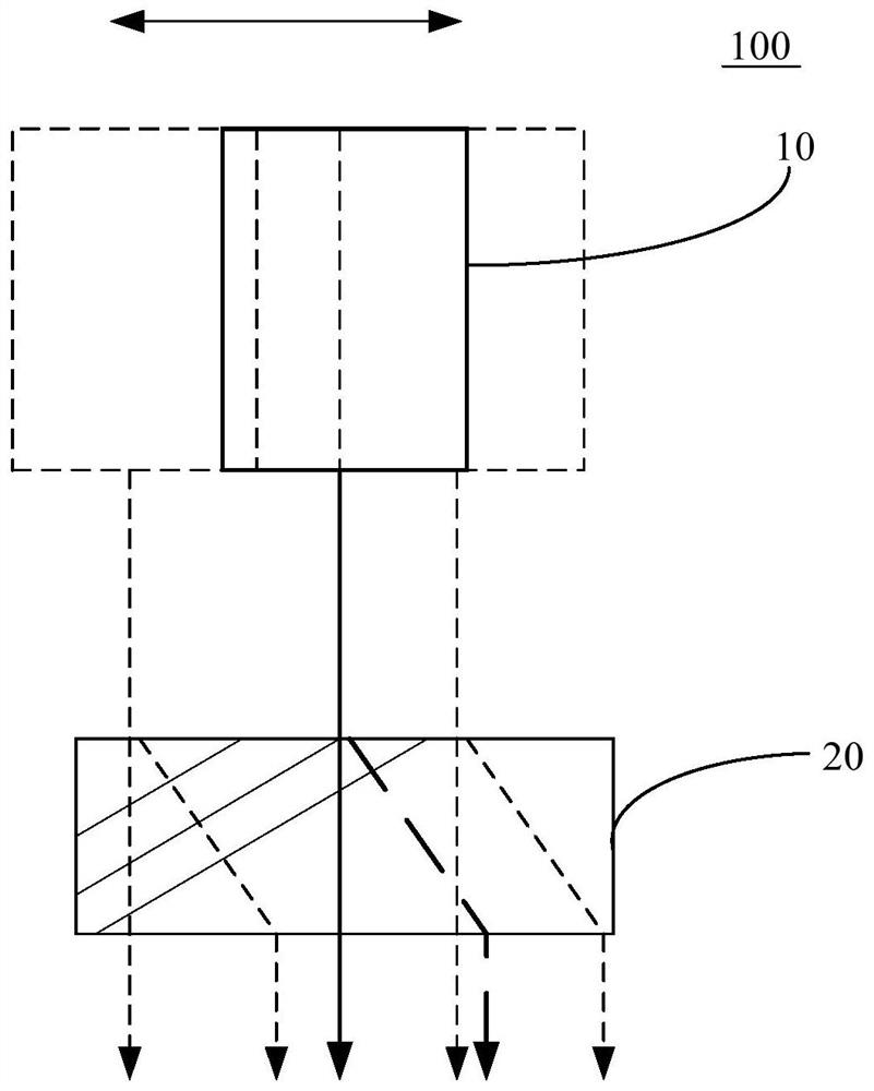
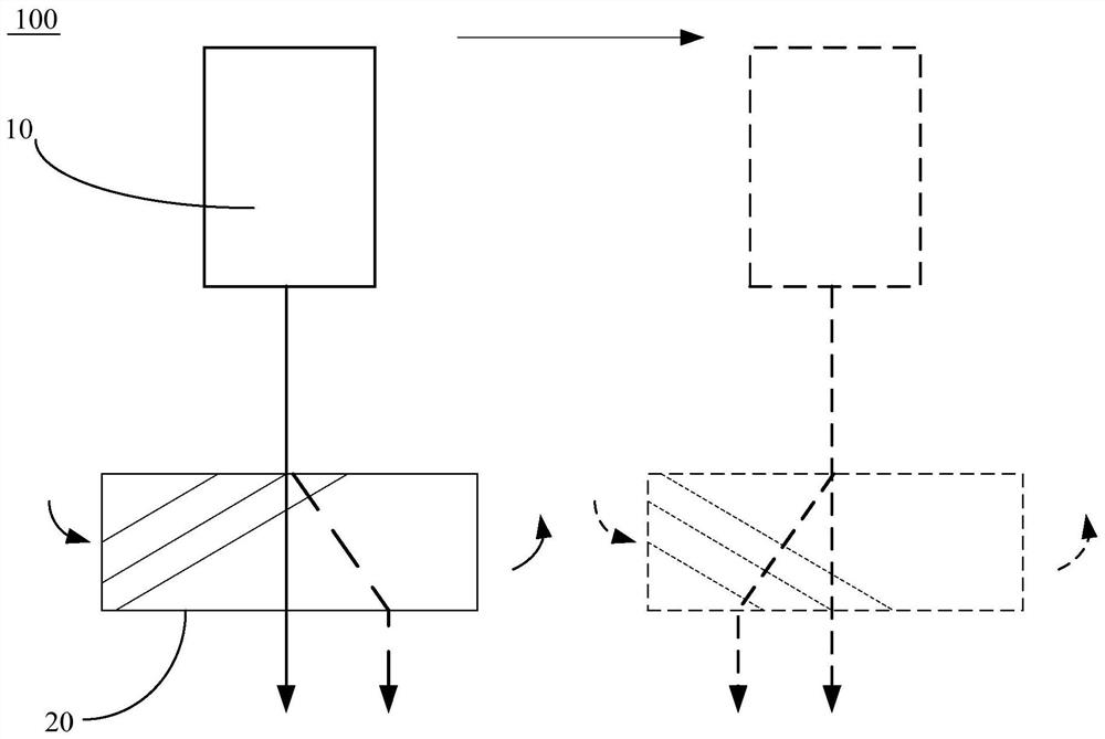
[0004] The main purpose of this application is to provide an optical component and an AR device, aiming to solve the problem that the current smart AR device is difficult to expand the orbital movement, so as to improve the user experience as a whole

Method used


Image

  • Optical assembly and AR equipment
  • Optical assembly and AR equipment
  • Optical assembly and AR equipment

Examples


Embodiment Construction

[0025] The following will clearly and completely describe the technical solutions in the embodiments of the present application with reference to the accompanying drawings in the embodiments of the present application. Obviously, the described embodiments are only part of the embodiments of the present application, not all of them. Based on the embodiments in this application, all other embodiments obtained by persons of ordinary skill in the art without creative efforts fall within the protection scope of this application.

[0026] It should be noted that all directional indications (such as up, down, left, right, front, back...) in the embodiments of the present application are only used to explain the relationship between the components in a certain posture (as shown in the drawings). Relative positional relationship, movement conditions, etc., if the specific posture changes, the directional indication will also change accordingly.

[0027] In addition, the descriptions in...


PUM

PropertyMeasurementUnit
thicknessaaaaaaaaaa

Abstract

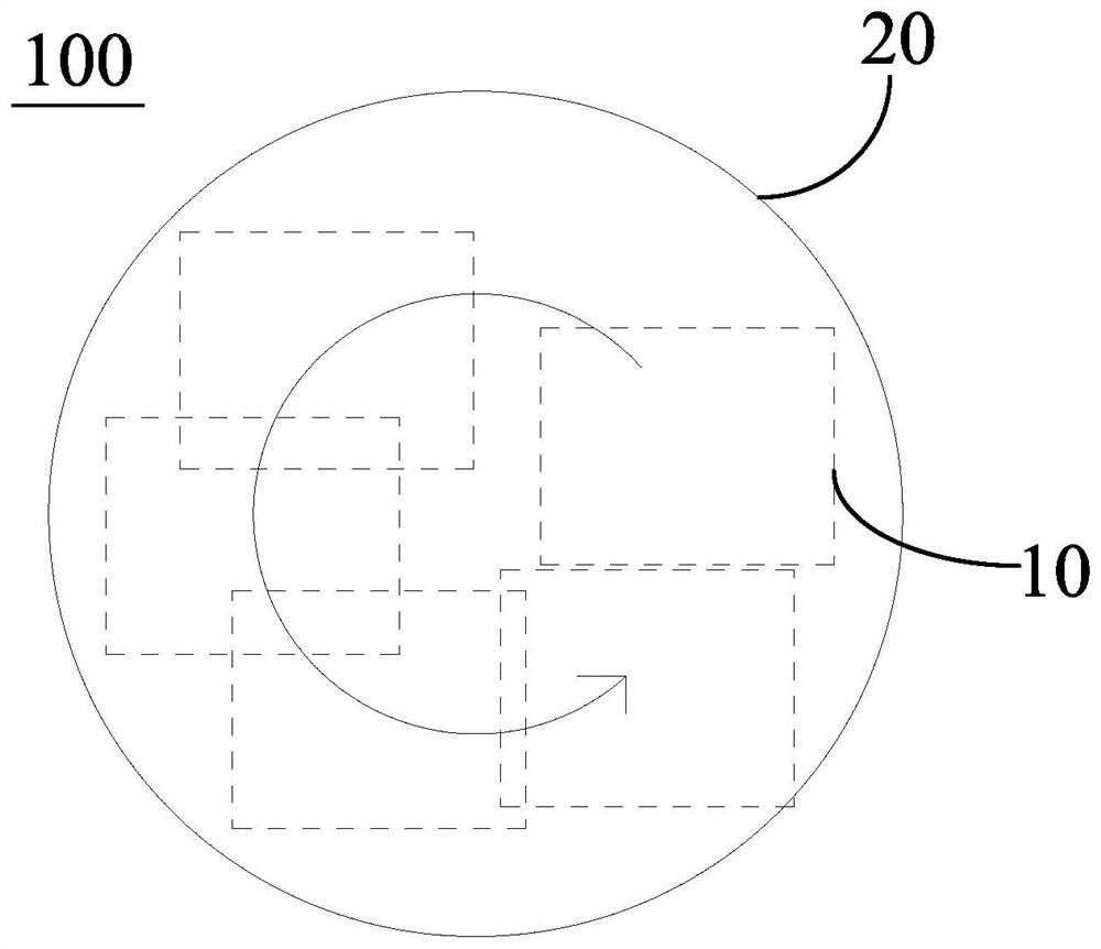
The embodiment of the invention provides an optical assembly and AR equipment, the optical assembly is applied to the AR equipment, and the optical assembly comprises: a display assembly; and an optical element based on a birefringence effect, wherein the optical element and the display assembly are arranged at an interval, at least part of light emitted by the display assembly vertically enters the incident plane of the optical element, the optical element converts at least part of light from the display assembly into o light and e light and emits the o light and the e light, and the opticalelement and the display assembly can move relative to each other so as to expand the emitting range of the e light. According to the technical scheme, the optical element based on the birefringence effect is arranged on the light path emitted by the display assembly, at least part of light emitted by the display assembly is converted into o light and e light through the optical element, the optical element and the display assembly move relatively so that the emitting range of the e light can be enlarged, and the user experience is improved as a whole.

Description

technical field [0001] The present application relates to the technical field of smart devices, in particular to an optical component and an AR device. Background technique [0002] AR devices are intelligently connected devices between the virtual world and the real world. Through AR glasses, the real world and virtual content can be seen, and visual, auditory and other information interactions can be performed. [0003] However, current smart AR devices, especially head-mounted augmented reality near-eye display devices, mostly use diffractive optical waveguides to expand the range of moving eye frames. Usually, the range of the orbit is strongly related to the size of the outcoupling area, and expanding the orbit can enhance the user experience. However, it is more difficult to expand the orbital movement. Contents of the invention [0004] The main purpose of this application is to provide an optical component and an AR device, aiming to solve the problem that the cu...

Claims


Application Information

Patent Timeline
Patent Type & Authority Applications(China)
IPC IPC(8): G02B27/01
CPCG02B27/0172G02B2027/0178
Inventor 朱瑞惠晓辉李德华
Owner GOERTEK OPTICAL TECH CO LTD
Why Eureka
Try Eureka