
Novel rolling-drawing die frame

A roll-pulling and die-set technology, applied in the field of roll-pull die set, can solve the problems of limiting the use range of profiles, the disc shape of profiles, the flatness, and the difficulty of stable control of ring diameter, so as to improve the processing quality and improve the stretching effect. Effect

Active Publication Date: 2021-04-06
广州众山精密科技有限公司
View PDF8 Cites 0 Cited by
  • Summary
  • Abstract
  • Description
  • Claims
  • Application Information

AI Technical Summary

Problems solved by technology

[0005] How to solve the problem that it is difficult to stably control the shape, flatness and ring diameter of profiles in the production process of the existing scheme, which limits the use range of this type of profiles

Method used


Image

  • Novel rolling-drawing die frame
  • Novel rolling-drawing die frame
  • Novel rolling-drawing die frame

Examples


Embodiment 1

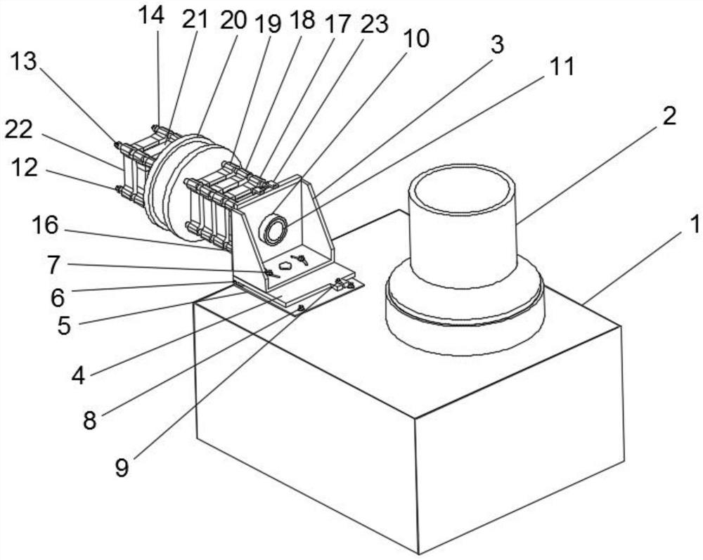
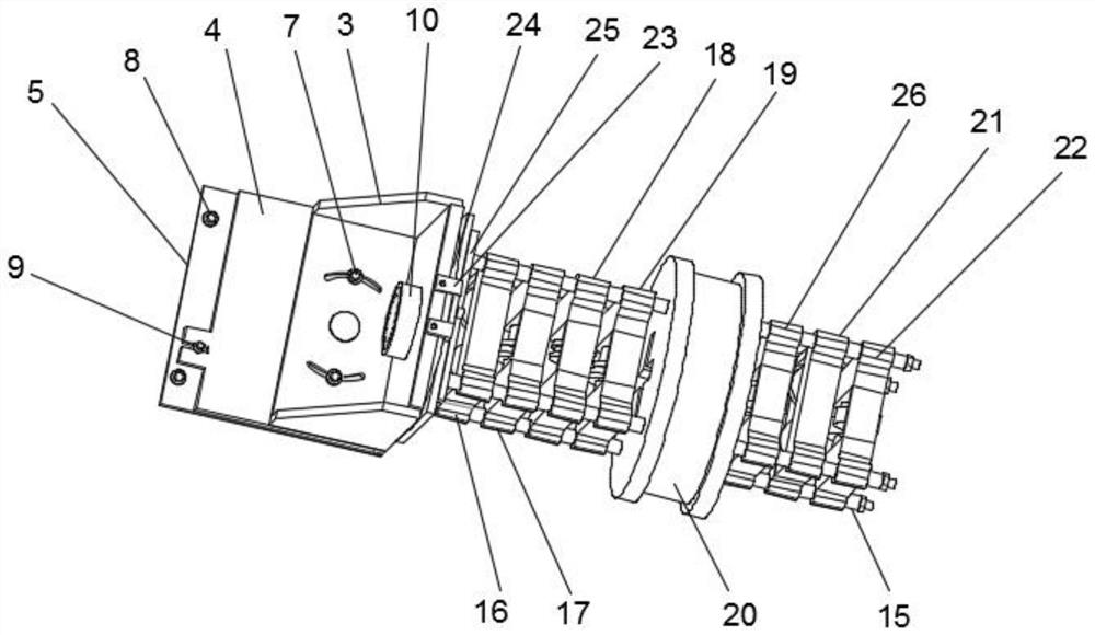
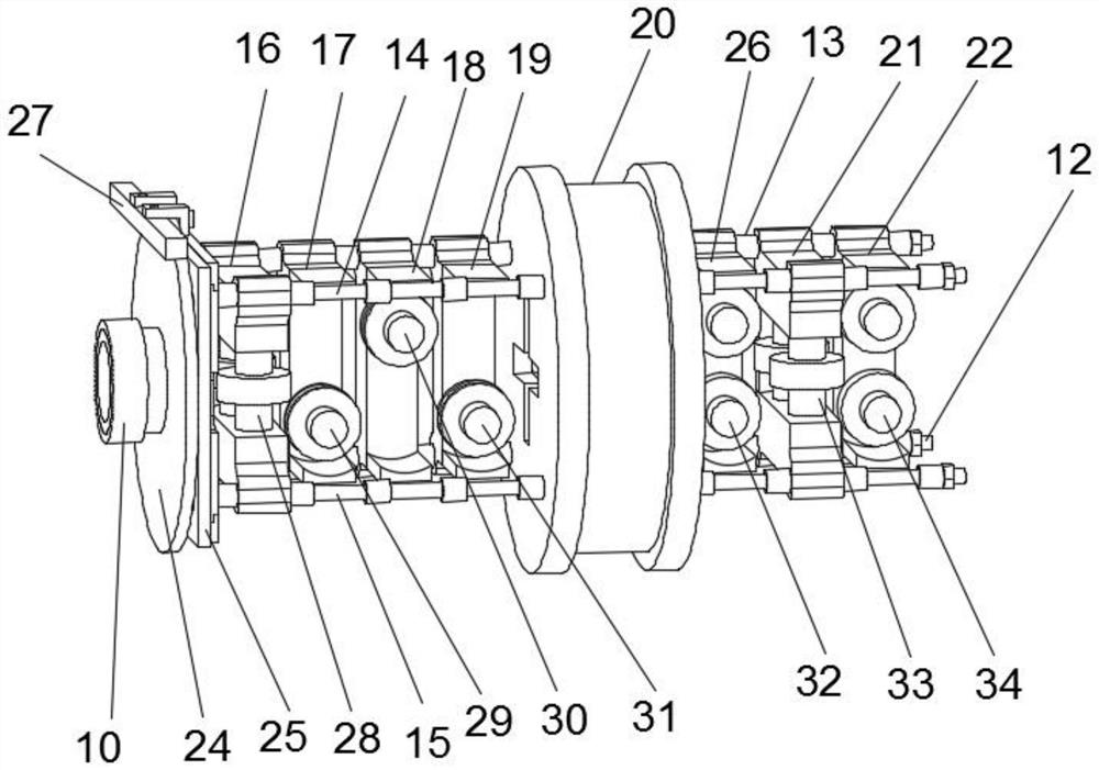
[0034] Such as Figure 1-5As shown, a new type of rolling formwork includes a support base 1, a roller 2, a connecting frame 3, a rotating plate 24, a first screw 12, a second screw 13, a third screw 14, a fourth screw 15 and a rolling mechanism 20. The roller 2 is installed on the upper end of the support base 1 near the front, the connecting frame 3 is connected to the upper end of the supporting base 1 near the rear, and the rotating plate 24 is rotatably connected to the rear end of the connecting frame 3 close to In the middle position, the middle position of the rear surface of the connecting frame 3 is provided with a connecting groove, the front end of the rotating plate 24 is fixedly connected with the limit ring 11, and the outer surface of the connecting frame 3 is fixedly equipped with a connecting ring 10;

[0035] The rear end of the rotating plate 24 is fixedly connected with a fixed plate 25, and the first screw 12, the second screw 13, the third screw 14 and t...

Embodiment 2

[0044] The working method of this novel rolling formwork comprises the following steps:

[0045] Step 1: pass the processing material between several fifth straightening rollers 34, between the second vertical rollers 33 and between the fourth straightening rollers 32, and pass through the rolling mechanism 20 through the rolling groove, and pass through the first A rolling wheel 35, a second rolling wheel 36, a third rolling wheel 37 and a fourth rolling wheel 38 roll the processing material, and the processing material is passed through the third straightening roller 31, the second straightening roller 30 and the straightening wheel on the first straightening roller 29 straighten the processed material;

[0046] Step 2: Pass the processing material through the positioning wheels on several first vertical rollers 28 for positioning, pass through the rotating plate 24 and the limit ring 11 and the drum 2 to wind and take up the wire, and after the processed material is taken u...


PUM


Abstract

The invention discloses a novel rolling-drawing die frame. The novel rolling-drawing die frame comprises a supporting base, a roller, a connecting frame, a rotating plate, a first screw, a second screw, a third screw, a fourth screw and a rolling-drawing mechanism, wherein the roller is arranged at the position, close to the front portion, of the upper end of the supporting base, the connecting frame is connected to the position, close to the rear portion, of the upper end of the supporting base, the rotating plate is rotationally connected to the position, close to the middle, of the rear end of the connecting frame, a connecting groove is formed in the middle of the rear surface of the connecting frame, a limiting ring is fixedly connected to the front end of the rotating plate, a connecting ring is fixedly arranged on the outer surface of the connecting frame, the first screw, the second screw, the third screw and the fourth screw are all fixedly mounted at the rear end of the connecting frame, and the first screw is located below the second screw. According to the Novel rolling-drawing die frame, the problems that the disc shape, the flatness and the ring diameter of a sectional material are difficult to stably control in the production process and the application range of the sectional material is limited in the existing scheme can be solved.

Description

technical field [0001] The invention relates to the technical field of rolling formwork, in particular to a novel rolling formwork. Background technique [0002] For the processing of simple cross-section profiles such as elastic materials, the traditional method generally uses a fixed mold to draw complex cross-section profiles. Because the fixed mold is difficult to make, it cannot be produced with a fixed mold. At present, the combined rolling mechanism is generally used for drawing production. Both traditional fixed molds and combined molds cannot be used for stable mass production of complex cross-section profiles with technical performance requirements. [0003] The disadvantages of the existing rolling formwork include: it is difficult to stably control the shape, flatness, and ring diameter of the profile during the production process, which limits the scope of use of this type of profile. Contents of the invention [0004] The object of the present invention is t...

Claims


Application Information

Patent Timeline
IPC IPC(8): B21D3/05B21C47/14
CPCB21C47/14B21D3/05
Inventor 朱华明邱树生周毅军郑玉坤贺霞肖林平兰昌飞阙忠泳
Owner 广州众山精密科技有限公司
Learn More