Cable detection device

A detection device and cable technology, applied in the field of cables, can solve the problems of decreased efficiency, occupation of large digital resources and consumption of detection time, increase of automatic detection costs, etc., to achieve modularization of circuit functions, optimization of I/O port utilization, and convenience. The effect of replacing the relay board

Pending Publication Date: 2021-04-06
CHINA ELECTRONICS TECH GRP CORP NO 14 RES INST
View PDF0 Cites 0 Cited by
  • Summary
  • Abstract
  • Description
  • Claims
  • Application Information

AI Technical Summary

Problems solved by technology

Using conventional methods can undoubtedly provide detailed and comprehensive test results, but its disadvantage is that after a certain line of the cable under test inputs a driving signal, it is not only necessary to check whether the output port of the line under test has received a drive signal, but also to To detect whether there is a "short circuit" or "wrong connection" relationship between the line to be tested and other lines in the cable, it is necessary to perform "traversal" query on all output ports of the cable to be tested
[0005] The conventional "traversal" automatic query method needs to occupy a large amount of digital resources and consume detection time, resulting in an increase in the cost of automatic detection and a decrease in efficiency

Method used


Image

  • Cable detection device
  • Cable detection device
  • Cable detection device

Examples


Embodiment Construction

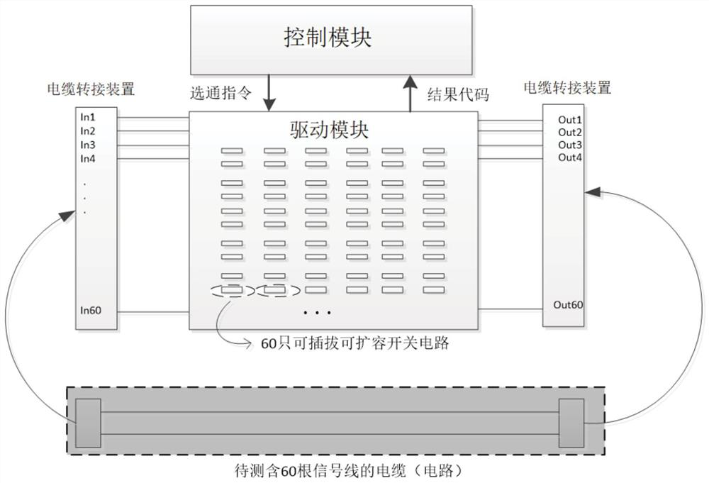
[0032] The cable detection device proposed by the present invention will be described in detail below in conjunction with the accompanying drawings.

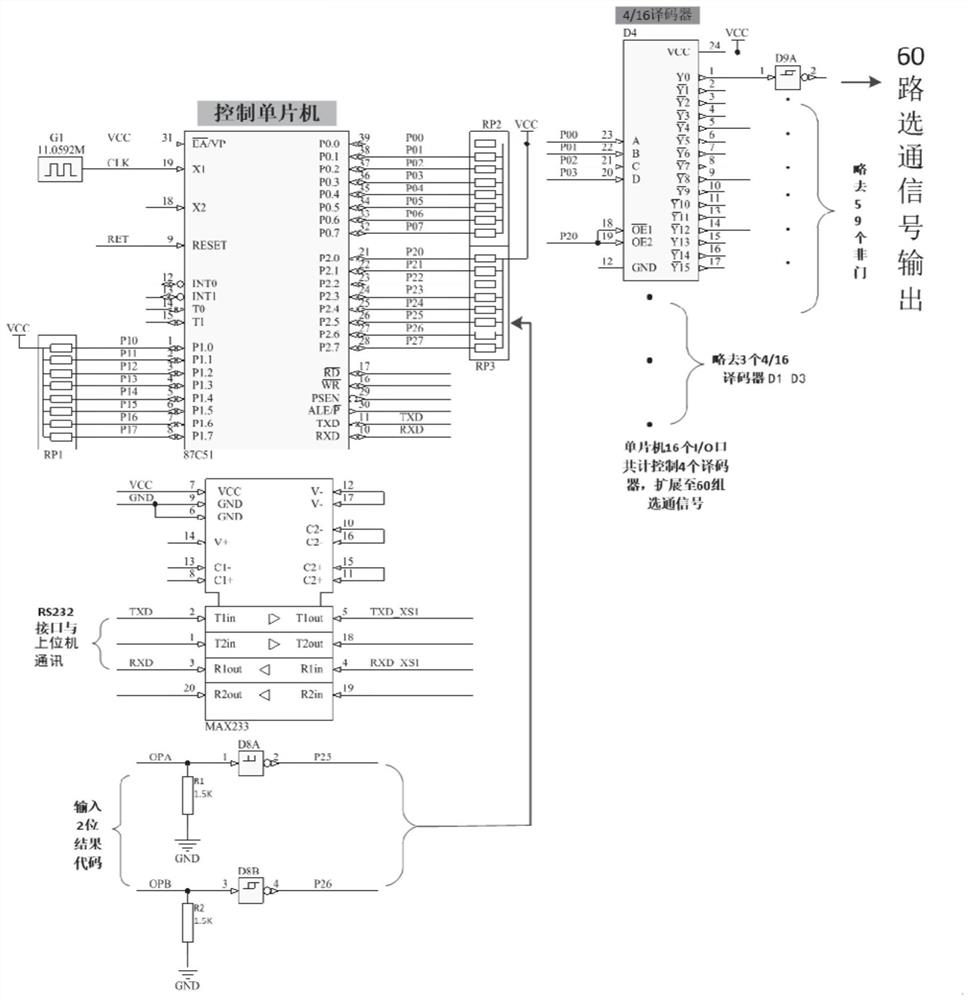
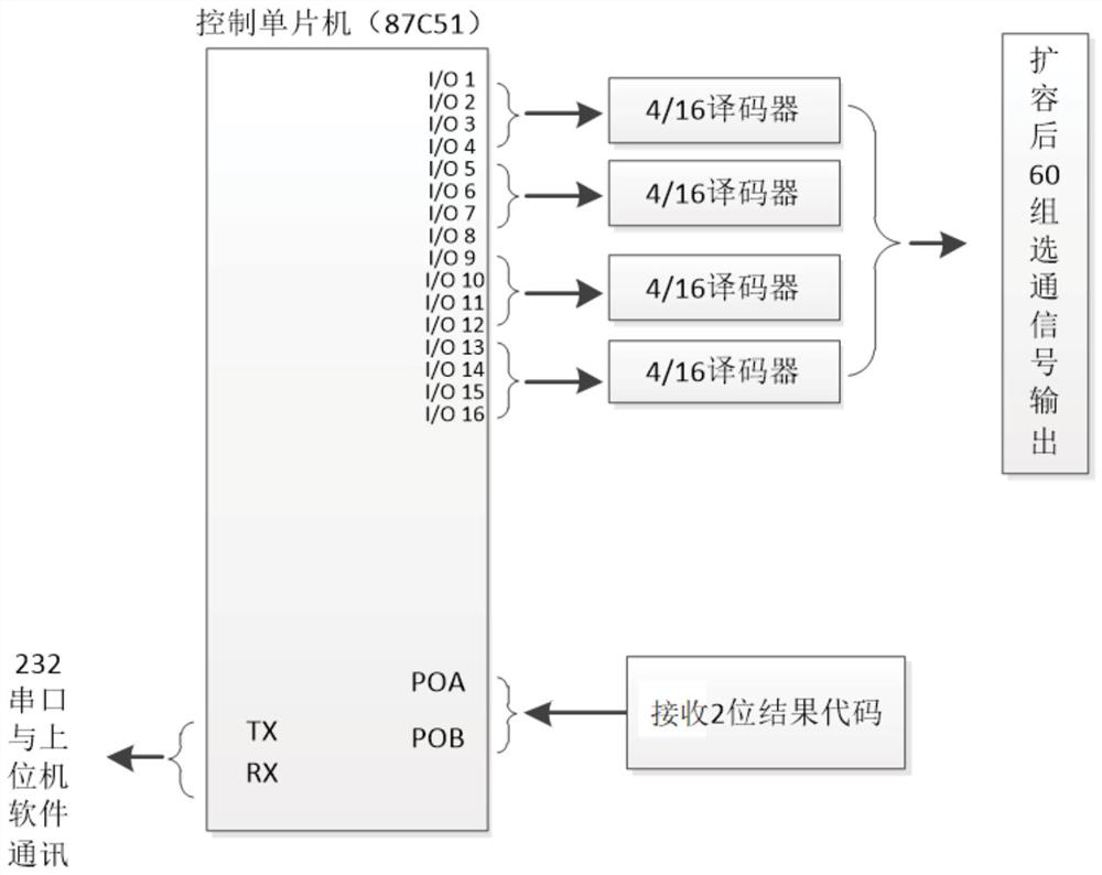
[0033] Such as figure 1 As shown, the cable detection device of the present invention includes a host computer, a control module, a drive module and a cable transfer device, the control module is connected to the drive module, and the drive module is connected to the cable to be tested through the cable transfer device. The control module sends strobe signals to the drive module in turn according to the detection instructions of the host computer; the drive module includes a drive circuit and a plurality of switch circuits, and the drive circuit sends and receives strobe signals from the control module to a plurality of switch circuits in turn, and the plurality of switches The circuit is sequentially turned on according to the strobe signal and the result signal is fed back to the control circuit through the drive circuit, and ...


PUM


Abstract

The invention discloses a cable detection device, which comprises an upper computer, a control module, a driving module and a cable switching device, and is characterized in that the control module is connected with the driving module, and the driving module is connected with a to-be-detected cable through the cable switching device; the control module sends gating signals to the driving module in sequence according to a detection instruction of the upper computer; and the driving module comprises a driving circuit and a plurality of switching circuits, the driving circuit sequentially sends gating signals from the control module to the switching circuits, the switching circuits are sequentially switched on according to the gating signals and feed result signals back to the control circuit through the driving circuit, and the control circuit feeds the result signals back to the upper computer. A single-chip microcomputer program control mode is adopted, an upper computer is controlled through a serial port, a relatively simple circuit mode of a relay is controlled through a decoder, and a multi-line automatic electrical detection mode is optimized.

Description

technical field [0001] The invention relates to the field of cables, in particular to a cable detection device. Background technique [0002] With the development of highly integrated circuit technology, more and more signal relations in the national defense and civilian fields are connected through dense cables or switching circuits, and the demand for automatic electrical detection of cables or circuits is also increasing. [0003] Cable (circuit) automatic electrical detection is actually an automatic "error checking" circuit, and it is necessary to judge whether there are "open circuit", "open circuit" and "wrong connection" between the terminals of the cable (circuit) to be tested. [0004] The conventional method is to input the drive signal in sequence to a certain line input port of the cable and circuit to be tested, and then detect all the output ports. Using conventional methods can undoubtedly provide detailed and comprehensive test results, but its disadvantage...

Claims


Application Information

Patent Timeline
Patent Type & Authority Applications(China)
IPC IPC(8): G01R31/58
CPCG01R31/58
Inventor 石浩杨军蒋敏玉
Owner CHINA ELECTRONICS TECH GRP CORP NO 14 RES INST
Why Eureka
Try Eureka