Display cabinet

A display cabinet and loading technology, which is applied in the field of display cabinets, can solve the problems of reduced storage capacity of sales commodities, excessive upper and lower dimensions of commodity racks, and unsatisfactory problems, so as to increase the effective volume, reduce the number of parts, and reduce the The effect of small top and bottom sizes

Active Publication Date: 2021-04-16
FUJI ELECTRIC CO LTD
View PDF7 Cites 1 Cited by
  • Summary
  • Abstract
  • Description
  • Claims
  • Application Information

AI Technical Summary

Problems solved by technology

In addition, since the shelf board is arranged above the bracket member, there is a possibility that the vertical dimension of the product rack may become too large.
In this way, if the upper and lower dimensions of the product rack are too large, the storage capacity of the sold products will be reduced, which is not ideal.

Method used


Image

  • Display cabinet
  • Display cabinet
  • Display cabinet

Examples


Embodiment approach 1

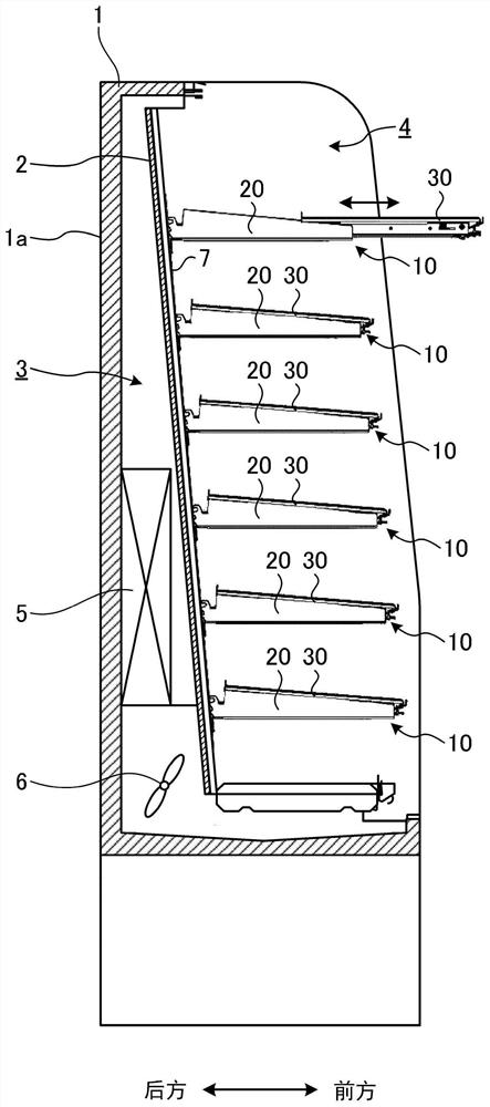
[0095]figure 1 A cross-sectional side view showing a display cabinet according to an embodiment of the present invention. In this case, the display cabinet will be stored in a convenient store and other shops, and the sales item is stored in the interior of the cabinet main body 1. In the first embodiment, in particular, a refrigerating display cabinet for accommodating a refrigerating product is exemplified.

[0096]That is, in the present display case, the back panel 2 is disposed in the inside of the cabinet main body 1, thereby constituting a venting conduit 3 between the rear wall 1a of the cabinet main body 1, and consists of relying forward more than the back panel 2 Storage room 4. An evaporator 5 is disposed inside the ventilation conduit 3, and the air fan 6 is provided. The evaporator 5 and the condensing unit (not shown) form a refrigeration cycle, and heat exchange between the passed air. In the display cabinet, when the condensing unit and the air blowing fan 6 are not sh...

Embodiment approach 2

[0130]Figure 16 A cross-sectional side view showing the display cabinet of the second embodiment of the present invention. For example, the display case exemplified is, for example, in a shop such as a convenience store, the merchandise is stored in the interior of the cabinet main body 51. In the second embodiment, in particular, a refrigerating display cabinet for accommodating a refrigerated product is exemplified.

[0131]That is, in the present display case, the back panel 52 is provided in the inside of the cabinet body 51, thereby constituting a venting conduit 53 between the rear wall 51a of the cabinet body 51, and constitutes a front than the back panel 52 Storage room 54. An evaporator 55 is disposed inside the venting conduit 53, air fan 56. The evaporator 55 and the condensing unit (not shown) together constitute a refrigeration cycle, and heat exchange between the passed air. In the display cabinet, when the condensing unit and the air blowing fan 56 are not shown, the ai...


PUM


Abstract

The utility model discloses a display cabinet which can reduce the manufacturing cost and increase the storage capacity of sold commodities. In the display cabinet, a commodity carrying frame (10) is formed, a support member (20) of the commodity carrying frame (10) is configured in a manner that the support member (20) faces forwards in a cabinet main body (1) with a front surface opening (1b), and a frame plate (30) of the commodity carrying frame (10), which is mounted on the support member (20) through a sliding piece (40), can slide in the front-back direction. The support member (20) is formed such that the upper end surface (22a) gradually tilts upward as the bracket member (20) faces rearward, and the bracket plate (30) is disposed such that the front end portion is supported by the bracket support shaft (316) on the inside of the slider (40) to form a component (42), and such that the rear end portion can swing up and down with respect to the inside component (42). And an inclined member (22) that is mounted on the upper end surface (22a) of the holder member (20) and forms an inclined posture.

Description

[0001]The patent application of the present invention is a schematic application application No. 2019104505553.x, an invention patent application name is a "display cabinet".Technical field[0002]The present invention relates to a display cabinet, more in more detail, involving an improvement in a display cabinet, such as a shop for convenience store and has a commodity mount for placement of the goods in the interior of the cabinet.Background technique[0003]In the past, for example, in shops such as convenience stores, most of them use a display cabinet that sells the goods to be placed in the interior of the cabinet main body. The merchandise carrier is composed of a slider to support the plateboard between the left and right bracket members.[0004]In the above display cabinet, a display cabinet is also provided to make the sales item easier to see as a purpose, or placed in the rear in the case where the goods placed in front of the merchandless frame are taken out. The sales commo...

Claims


Application Information

Patent Timeline
Patent Type & Authority Applications(China)
IPC IPC(8): A47F3/04A47F3/06A47F3/14
CPCA47F3/0443A47F3/063A47F3/14
Inventor 泽村善纪木下卓
Owner FUJI ELECTRIC CO LTD
Why Eureka
Try Eureka