
Device for comminuting loose feed material

An equipment and grinding technology, applied in the field of feeding equipment, can solve the problem that the grinding equipment is not fully utilized, and achieve the effect of optimizing the possibility

Active Publication Date: 2021-04-16
SIEMPELKAMP MASCH & ANLAGENBAU GMBH & CO KG
View PDF4 Cites 0 Cited by
  • Summary
  • Abstract
  • Description
  • Claims
  • Application Information

AI Technical Summary

Problems solved by technology

However, it must be accepted here that the crushing plant is not fully utilized, which contradicts the basic requirements for the economical operation of such plants

Method used


Image

  • Device for comminuting loose feed material
  • Device for comminuting loose feed material
  • Device for comminuting loose feed material

Examples


Embodiment Construction

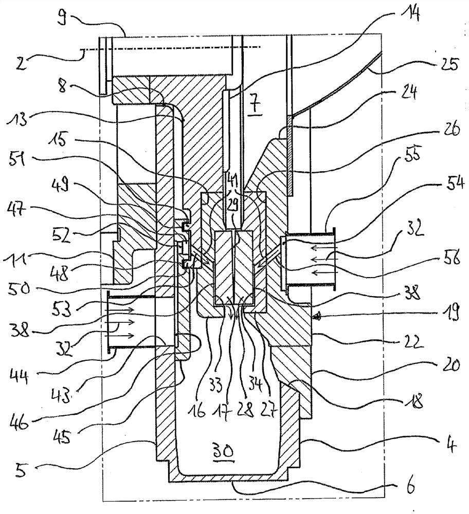
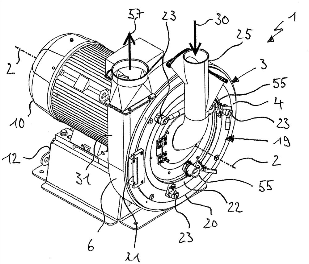
[0023] Figures 1 to 3 The basic structure of the device according to the invention in the form of a disc refiner 1 is shown. The disc refiner 1 has a substantially drum-shaped housing 3 surrounding an axis 2 with a front wall 4, a rear wall 5 axially spaced therefrom and a housing casing 6 connecting the front wall 4 and the rear wall 5, which Surround the crushing space 7 together.

[0024] In the region of the axis 2 , the rear wall 5 has a housing opening 8 coaxial with respect to the axis 2 , through which the end of the drive shaft 9 of the drive unit extends. In the present embodiment, the drive shaft 9 is formed directly by the rotor shaft of the electric motor 10 , but it can also be driven as a separate shaft indirectly via a belt drive or other transmission means. The housing 3 is rigidly connected via an annular flange 11 concentrically surrounding the housing opening 8 to an electric motor 10 , which in turn rests on a stationary base 12 .

[0025] especially f...


PUM


Abstract

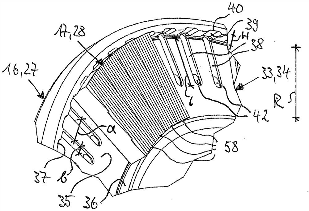
The invention relates to a device for comminuting feed material with first comminuting tools (17) and second comminuting tools (28), which are arranged inside a housing (3) coaxially to an axis (2) and which are axially spaced apart to form a comminuting zone (29), and of which at least the first comminuting tools (17) perform a rotational movement about the axis (2). The first comminuting tools (17) are rigidly attached to a first tool carrier (16) and the second comminuting tools (28) are rigidly attached to a second tool carrier (27). According to the invention it is proposed that in the contact area between the first tool carrier (16) and the first comminuting tools (17) and / or in the contact area between the second tool carrier (27) and the second comminuting tools a number of channels for the passage of a process gas are provided. The channels each have a radially inner inlet opening through which the process gas enters the channels and a radially outer outlet opening through which the process gas emerges from the channels (38). Among other things, this achieves improved cooling of the comminuting zone.

Description

technical field [0001] The invention relates to a device for comminuting pourable feedstock according to the preamble of claim 1 . Background technique [0002] Plants of the type mentioned at the outset are characterized by the air-through-flow mode of operation, in which the air and the feed material are introduced axially as a gas-solid mixture into the grinding space and, after a radial deflection, enter the annular In the grinding gap formed by the crushing tool. After grinding there to the desired size, the sufficiently fine material emerges radially from the grinding gap and accumulates in the circumferential annular channel between the housing and the grinding tool, from where it is discharged tangentially from the device in the air flow . [0003] In this case, the energy to be applied during crushing is largely converted into heat. The reason for this is the frictional, shearing and impacting forces which the feed material is subjected to during the crushing and...

Claims


Application Information

Patent Timeline
Patent Type & Authority Applications(China)
IPC IPC(8): B02C7/06B02C7/11B02C7/17B02C23/02B02C23/24
CPCB02C7/17B02C7/04B02C7/06Y02W30/62B02C23/26
Inventor B·阿勒斯
Owner SIEMPELKAMP MASCH & ANLAGENBAU GMBH & CO KG
Learn More