Method for producing cooled power electronics module

A technology for power electronic modules and cooling channels, applied in semiconductor/solid-state device manufacturing, circuits, electrical components, etc., can solve problems such as damage to eddy currents, and achieve stable manufacturing or connection effects

Pending Publication Date: 2022-01-14
VOLKSWAGEN AG
View PDF3 Cites 0 Cited by
  • Summary
  • Abstract
  • Description
  • Claims
  • Application Information

AI Technical Summary

Problems solved by technology

Here, in the case of power electronics modules that could theoretically be used for cooling, the problem arises that the swirlers can be damaged during sintering of the electronic components to be cooled

Method used


Image

  • Method for producing cooled power electronics module
  • Method for producing cooled power electronics module
  • Method for producing cooled power electronics module

Examples


Embodiment Construction

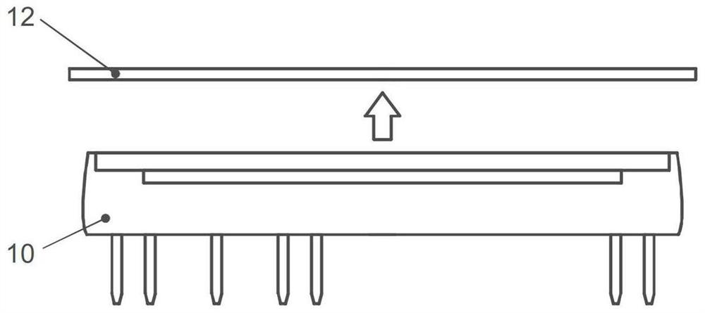
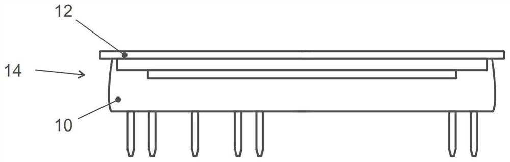
[0028] figure 1 The thermal and mechanical connection of the electronic component 10 to the cooling channel cover 12 designed as a flat sheet metal is schematically shown. The details of the electronic component 10 are not important in the context of the present invention. In particular, however, it may be a switching element for power electronics for the operation of a traction machine of a motor vehicle. Preferably, the electronic component 10 is in its figure 1 The upper side shown in the middle pointing upwards has a sinterable coating which is sintered with the corresponding material on the lower side of the cooling channel cover 12 in order to thereby produce a tight, material-bonded thermal and mechanical connection. connect. produced as in figure 2 The prefabricated modules 14 shown schematically in .

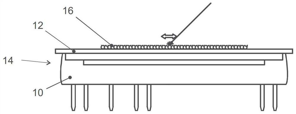
[0029] Next, in image 3 In the method steps shown, the swirler structure 16 is applied to the upper side of the cooling channel cover 12 by means of 3D printing...


PUM


Abstract

The invention relates to a method for producing a cooled power electronics module, comprising the following steps: providing a prefabricated module (14), which comprises a plate-shaped cooling channel cover (12) and at least one electronic component (10) that is integrally bonded and is in thermal contact with an underside of the cooling channel cover (12); 3D-printing a metal swirler structure (16) on the upper side of the cooling channel cover (12) in a region opposite the electronic component (10); and encapsulating the swirler structure (16) in a fluid-conducting housing which is provided with a fluid inlet (181) and a fluid outlet and which is connected to the upper side of the cooling channel cover (12) in a fluid-tight manner.

Description

technical field [0001] The invention relates to a method for producing a power electronics module, in particular for cooling a traction motor in a motor vehicle. Background technique [0002] Such a cooled power electronics module is known from document DE 10 2016 222 909 A1. [0003] The term "cooled" is not limited here to the currently cooled state; rather it should mean that the module in question has means that allow cooling of the electronic components contained in the module to be brought about when conventionally connected to the cooling fluid line system. [0004] The cited document describes the production by means of 3D printing of a heat sink consisting of an electrically insulating outer jacket and a highly thermally conductive core. The term "3D printing" is to be understood in the context of the present invention as extended and synonymous with the term "additive manufacturing method"; this term includes in particular methods such as laser sintering, laser be...

Claims


Application Information

Patent Timeline
Patent Type & Authority Applications(China)
IPC IPC(8): H01L21/50H01L23/46H01L23/367H01L23/04
CPCH01L21/50H01L23/46H01L23/367H01L23/04H01L23/473H01L23/3733H01L21/4871
Inventor M.齐默曼S.利克O.朗
Owner VOLKSWAGEN AG
Why Eureka
Try Eureka