A simple laser bench clamping device with adjustable inclination angle

A technology of tilt angle and clamping device, which is applied in the direction of auxiliary equipment, laser welding equipment, auxiliary welding equipment, etc., can solve the problems that cannot meet the requirements of laser machining large-angle inclined hole processing technology research, unfavorable research funds, unfavorable experimental research, etc. Achieve the effects of simple and practical mechanical locking method, obvious economic superiority and improved stability

Inactive Publication Date: 2016-04-13
XI AN JIAOTONG UNIV
View PDF6 Cites 0 Cited by
  • Summary
  • Abstract
  • Description
  • Claims
  • Application Information

AI Technical Summary

Problems solved by technology

For the problem of how the angular displacement table can make the workpiece tilt at different angles, major photoelectric instrument manufacturers use arc-shaped guide rails to ensure the accuracy of movement, and the range of inclination travel achieved by using arc-shaped guide rails is very small, generally within ±3° ~±30°, which cannot meet the requirements of laser processing for large-angle inclined hole processing technology research
The multi-angle displacement table adopts worm gear transmission. Although the precision and stability are high, its structure is compact and the processing is difficult. It requires high processing accuracy for each part and high process requirements. Therefore, the cost of this type of angular displacement table is relatively high. Conducive to saving research funds
Recently, some people have designed a clamping device with tilt angle adjustment function to achieve a specific angle adjustment, but it cannot be adjusted arbitrarily within a certain angle range, the structure is complex, and the limitations are too large, which is not conducive to experimental research

Method used


Image

  • A simple laser bench clamping device with adjustable inclination angle
  • A simple laser bench clamping device with adjustable inclination angle
  • A simple laser bench clamping device with adjustable inclination angle

Examples


Embodiment Construction

[0016] The present invention will be further described below in conjunction with the accompanying drawings.

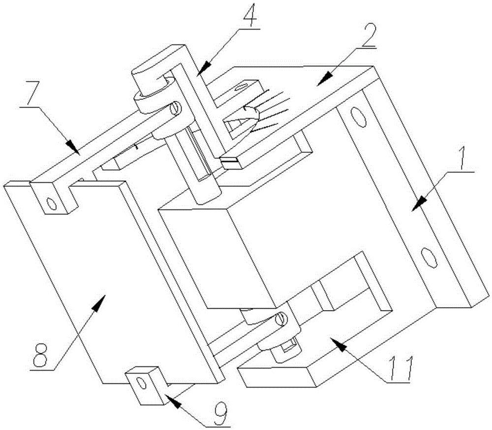
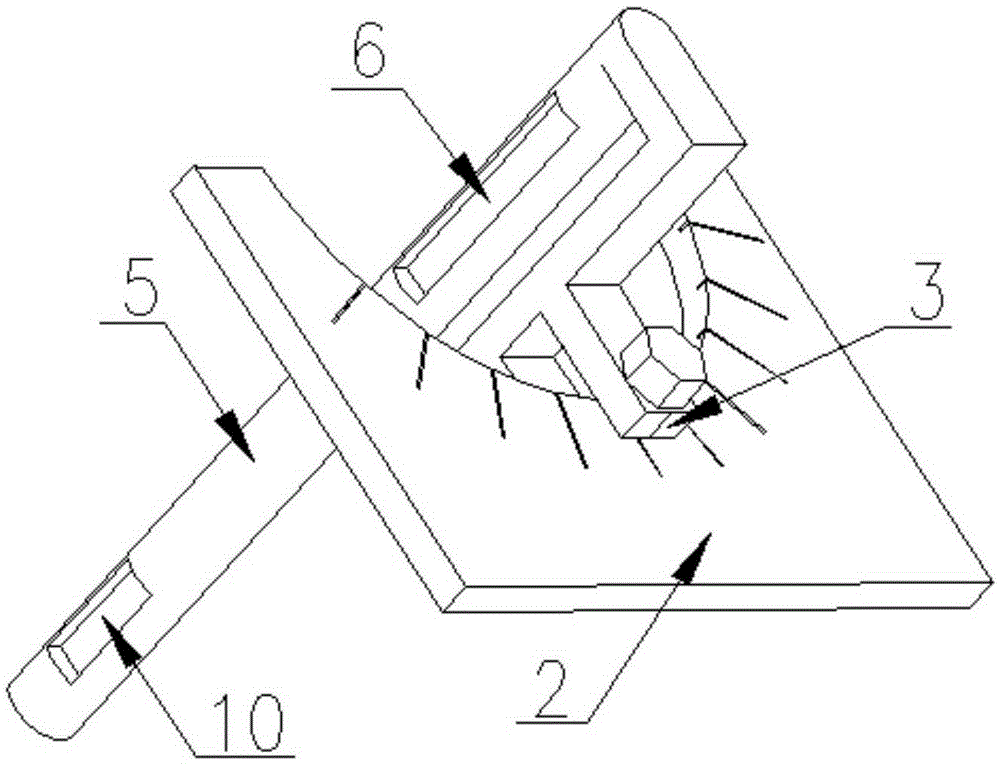
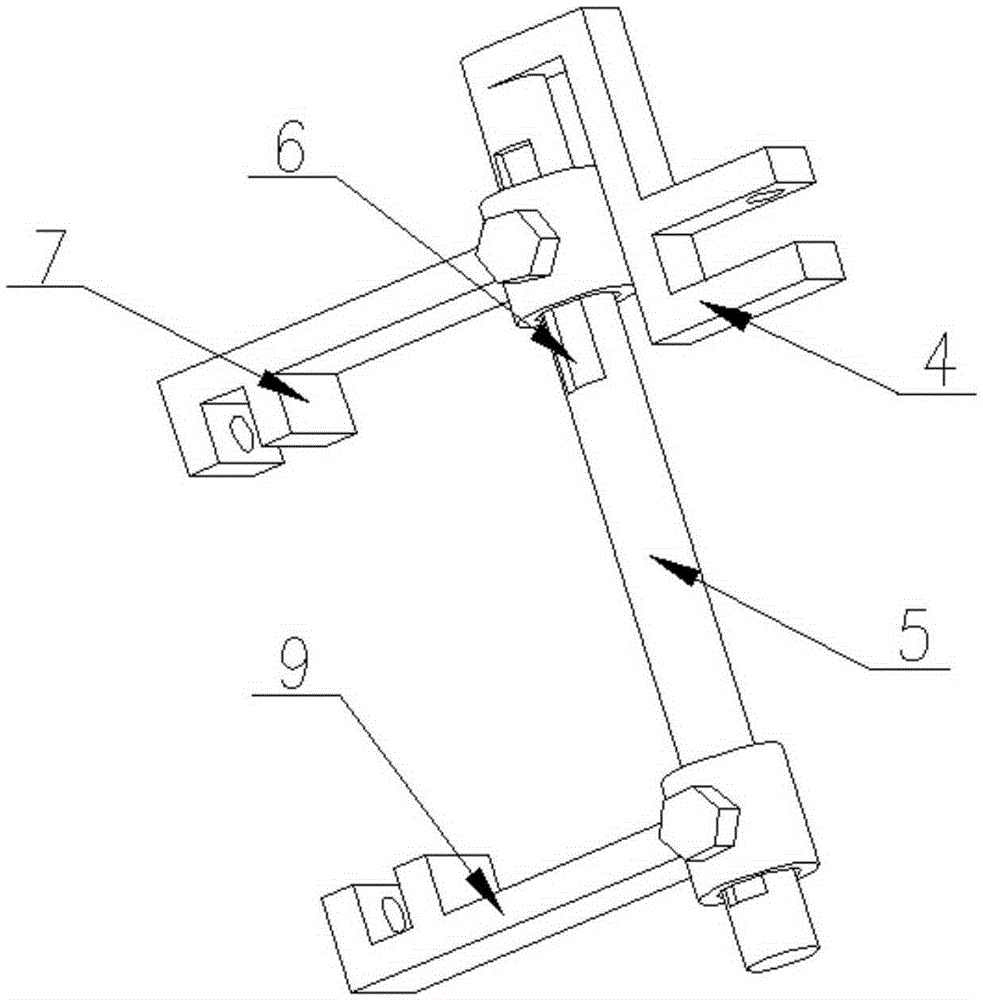
[0017] see figure 1 , a simple laser stand clamping device with adjustable inclination angle, including a base 1, with through holes on the four corners of the base 1, which are fixed on the moving table of the laser stand through bolt connection; the upper cover plate 2 is connected On the upper end of the base 1, the lower cover plate 11 is installed on the lower end of the base 1, the middle part of the main shaft 5 passes through the inner hole of the boss in the middle part of the base 1, the inner hole constrains the radial movement of the main shaft 5, and the lower end of the main shaft 5 is connected to the lower cover plate 11, so that the rotation of the main shaft 5 is more stable, and the upper end is connected with the upper cover plate 2 by bolts through the side clamp 4 welded on the main shaft 5 to constrain the axial movement of the main shaft 5, such...


PUM


Abstract

A simple laser rack clamping device with the adjustable inclination angle comprises a base. The base is fixedly connected to a laser rack moving tabletop through bolts. An upper cover board and a lower cover board are installed at the upper end and the lower end of the base. The middle of a spindle penetrates through an inner hole of a boss in the middle of the base. The lower end of the spindle is connected to the lower cover board and the upper end of the spindle is connected with the upper cover board through a side clamp on the spindle. The side clamp is provided with a compass. The upper cover is marked with scale marks of the rotating angle. The upper portion of the spindle is connected with an upper clamp and the lower portion of the spindle is connected with a lower clamp. A workpiece is fixed between the upper clamp and the lower clamp. The spindle rotates to drive the workpiece to rotate, so that the inclination angle of the workpiece fixed between the upper clamp and the lower clamp is generated. The rotating angle of the spindle is changed and determined by adjusting the included angle between a pointer and the scale marks of the upper cover board. According to the device, the inclination angle between the axis of a hole of the workpiece and a laser beam can be continuously adjusted within the range from -90 degrees to +90 degrees, operation is simple, and the experiment research requirements for machining perpendicular holes and inclined holes through lasers are met.

Description

technical field [0001] The invention relates to a clamping device, in particular to a simple laser stand clamping device with an adjustable inclination angle. Background technique [0002] The wide application of micro-holes in the aviation industry and precision instruments has made the micro-hole processing technology widely concerned by the scientific and engineering circles at home and abroad. As the temperature before the turbine of the aero-engine continues to increase, the hot-end parts of the engine adopt film cooling technology. Therefore, the quality of the film cooling hole is directly related to the quality of the film cooling effect. The inclination angle between the central axis of the film cooling hole and the surface varies from 30° to 90°. Therefore, in the experimental research of laser machining small holes, not only vertical hole processing, but also oblique straight hole processing need to be paid attention to. The motion platform of the laser configur...

Claims


Application Information

Patent Timeline
Patent Type & Authority Patents(China)
IPC IPC(8): B23K26/70B23K37/04B23K26/382
CPCB23K37/04
Inventor 王恪典吕静段文强凡正杰袁新李季昌
Owner XI AN JIAOTONG UNIV
Why Eureka
Try Eureka