Method of making dunnage bags

a bag and dunnage technology, applied in the field of transportation and shipment of goods, can solve the problems of prohibitively high time, trouble, and cost of using such bags, and achieve the effects of improving strength to weight ratio, reducing labor intensity, and reducing labor intensity

Inactive Publication Date: 2002-08-20
JOHN DAVID M
View PDF10 Cites 81 Cited by
  • Summary
  • Abstract
  • Description
  • Claims
  • Application Information

AI Technical Summary

Benefits of technology

A principal object of the present invention is to provide a dunnage bag which has the advantages of bags of prior art, that is be capable of being inflated with and retaining gas pressure, be resistant to bursting, abrasion and puncture from edges and corners of goods, but be more economical to manufacture, have an improved strength to weight ratio, be moisture resistant, may be reused if desired and be facilely recyclable.
To these ends the objects of the invention are to provide a gas impervious dunnage bag which is comprised of low cost materials, is easily manufactured, is burst resistant, has an outer surface resistant to bursting, abrasion and damage from edges and corners of goods, is moisture resistant, is reusable and is readily recyclable.
Another object of the invention is to provide a dunnage bag, the wall of which is comprised of an outer layer of woven strips of strong thermoplastic polymeric material which is resistant to moisture, bursting, abrasion or damage by cargo edges and corners and a continuous inner layer of gas impervious thermoplastic polymeric material integrally fused to said outer layer and is therefore sturdy, lightweight, easy and economical to use, reuse and / or recycle.
Yet other objects of the invention relate to providing a method of manufacturing the dunnage bag of the present invention in a rapid, economical and efficient manner.

Problems solved by technology

Because of their construction such bags were heavy, expensive to manufacture, and if to be reused (which their cost nearly mandated) had to be deflated (which was time consuming and could rarely be accomplished fully with the bag in the cargo container), handled carefully, carefully packed for return to the shipper, etc.
Accordingly, time, trouble and cost of using such bags was found to be prohibitively high.
Manufacture of the sleeve of gas impermeable liner within a sleeve of multiple layers of more resilient material remained expensive.
Also, metal clamps were expensive, were prone to leak in transit and unless positioned carefully were themselves capable of damaging dunnage bags, the cargo or its container and had to be returned to a shipper for reuse.
Also, while in theory the bladder material and outer material could be separated into different streams and each separately recycled, because of the cost of labor involved in separation, used bags were frequently disposed, creating waste disposal issues.
They are still relatively expensive to manufacture and use.
Inasmuch as outer layers of such bags, which give the bag most of its resistance to bursting, abrasion or puncture, consists of paper, such bags are susceptible to moisture, and while such bags are designed to be disposed of after single use, disposal is a problem.
While in theory the paper and the plastic components of the bags could be at least largely be separated and recycled appropriately, in practice that is almost never done because of labor costs involved, and separation would likely be incomplete even if attempted, because the ends of the bladder are typically glued into folds of the paper.
Hence near major receiving centers disposal of dunnage bags creates waste disposal issues.

Method used


Image

  • Method of making dunnage bags
  • Method of making dunnage bags
  • Method of making dunnage bags

Examples


Embodiment Construction

While the present invention will be described with reference to preferred embodiments, it will be understood by those skilled in the art that various changes may be made and equivalents may be substituted for elements thereof without departing from the scope of the invention. In addition, many modifications may be made to adapt a particular situation or material to the teachings of the invention without departing from the essential scope thereof. Therefore, it is intended that the present invention not be limited to the particular embodiments disclosed as the best mode contemplated for carrying out this invention, but that the invention will include all embodiments (and legal equivalents thereof) falling within the scope of the appended claims.

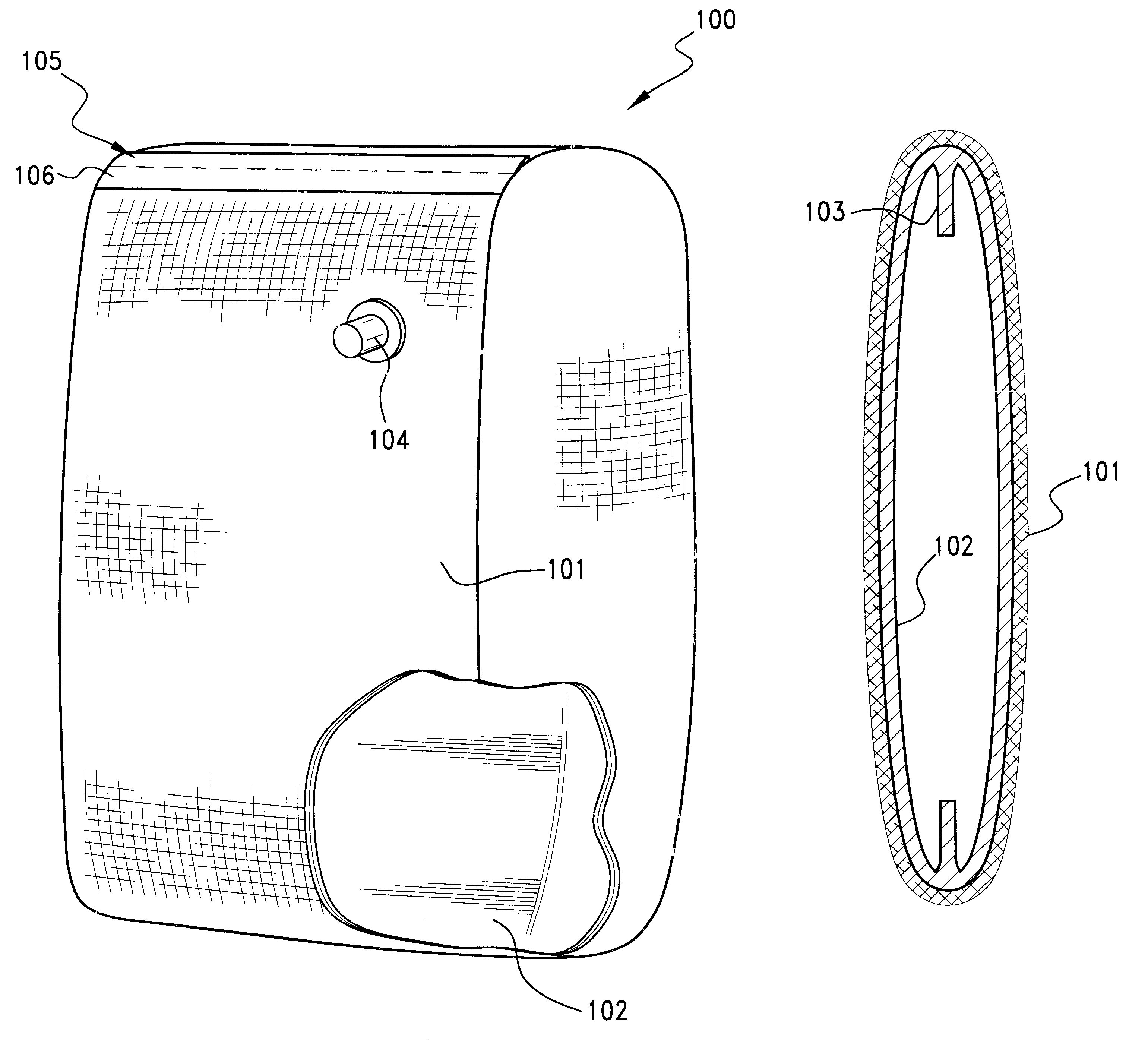
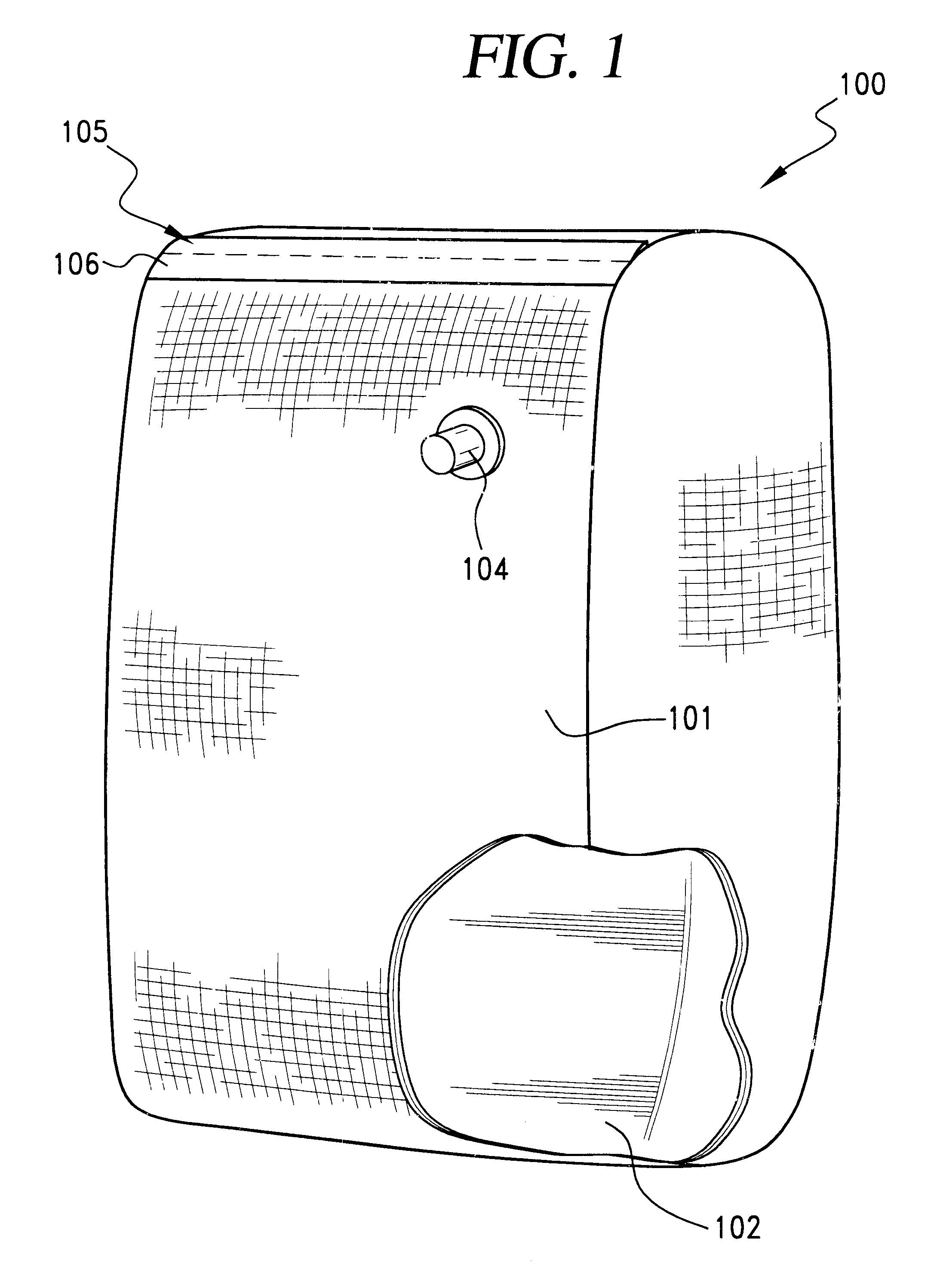
The preferred embodiment of the dunnage bag 100 of the present invention is generally characterized in FIG. 1. Outer layer 101 is composed of a woven sleeve of thermoplastic polymer strips, selected for resistance to moisture, stretching, burs...


PUM


Abstract

A method of manufacturing an inflatable dunnage bag having a wall construction of two integrally fused layers of thermoplastic polymer, the outer layer of which is a sleeve of strips of woven polymer, the inner of layer of which is a continuous layer of gas impervious polymer. The ends of the sleeve are sealed against the escape of gas. The wall of the bag has a valve for the admittance of gas to the interior of the bag. The bag is formed by deposition of a continuous molten layer of gas impervious polymer to a sleeve of strips of woven polymer, installing a valve for admittance of gas into the wall of the sleeve and forming a gas tight seal at the ends of the sleeve. Deposition of the continuous layer of gas impervious polymer may be a two-step process wherein a molten layer of gas impervious polymer is deposited to one exterior side of the flattened sleeve, then to the other exterior side of the flattened sleeve and the sleeve turned "inside-out". The ends of the bag are sealed, may be folded, the folds secured to the exterior of the bag by adhesive and a binding strip. The dunnage so manufactured is strong, lightweight, scuff resistant, moisture resistant, reusable or easily recyclable.

Description

BACKGROUND--FIELD OF THE INVENTIONIn the field of transportation and shipment of goods, "dunnage bags" are frequently used. Dunnage bags are inflatable structures, typically inflated with pressurized gas, designed to be disposed in the void spaces of a cargo container or hold.BACKGROUND--DESCRIPTION OF RELATED ARTIt is well conventionally practiced in the field of cargo transportation to place dunnage bags between individual, adjacent cargo pieces, or between the individual cargo pieces and the side walls of a cargo container or hold, to fill the voids within the container or hold and thereby prevent damage to the cargo pieces or walls of the container or hold due to shifting of cargo during transportation. Because dunnage bags are subjected to forces of cargo attempting to shift, they must be resistant to rupturing or leakage in an environment where the surface of the bag will be subject to abrasion, contact with edges and corners, etc.Previously known dunnage bags typically consis...

Claims


Application Information

Patent Timeline
Patent Type & Authority Patents(United States)
IPC IPC(8): B60P7/06
CPCB60P7/065
Inventor JOHN, DAVID M.
Owner JOHN DAVID M
Why Eureka
Try Eureka