Rubber tube end lubricating device

A technology for lubricating devices and rubber hoses, which is applied to devices for coating liquid on the surface, tubular objects, and other household appliances. It can solve the problems of increased labor intensity and low operating efficiency, and achieve the effect of ensuring the uniformity of oil receiving

Pending Publication Date: 2021-04-16
青岛橡六胶管有限公司 +2
View PDF13 Cites 2 Cited by
  • Summary
  • Abstract
  • Description
  • Claims
  • Application Information

AI Technical Summary

Problems solved by technology

During the processing of the rubber hose, a conveying device is usually required to realize the transportation of the rubber hose. In order to improve the conveying efficiency and stability of the rubber hose, it is usually necessary to apply lubricating oil or grease to the end of the rubber hose to reduce the friction coefficient at the end of the rubber hose. However, the operation efficiency of this method is low and the labor intensity is increased.

Method used


Image

  • Rubber tube end lubricating device
  • Rubber tube end lubricating device
  • Rubber tube end lubricating device

Examples


Embodiment Construction

[0026] The present invention will be described in further detail below in conjunction with the accompanying drawings and specific embodiments.

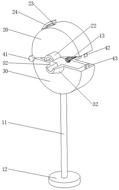
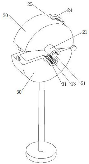
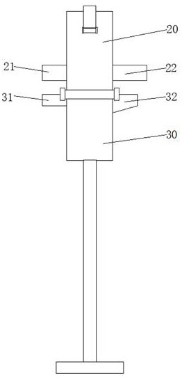
[0027] See Figure 1-3 As shown, the present invention proposes a rubber hose end lubricating device, which includes: a column 11 , a base 12 , an upper chamber 20 and a lower chamber 30 .

[0028] The column 11 is fixedly arranged on the base 12 , the column 11 is arranged along the vertical direction, and the top of the column 11 is connected to the bottom of the lower cavity 30 .

[0029] One side of the upper chamber 20 and the lower chamber 30 is connected by a rotating shaft 41, and the other side of the upper chamber 20 and the lower chamber 30 are snap-connected. One side of the upper chamber 20 is provided with an upper buckle 42, and one side of the lower chamber 30 is provided with a lower The buckle 43 , the upper buckle 42 and the lower buckle 43 are snapped together, thereby facilitating the opening or closing of the up...


PUM


Abstract

The invention provides a rubber tube end lubricating device which comprises an upper cavity and a lower cavity, wherein the upper cavity and the lower cavity are connected in an up-and-down buckling mode and used for containing sponge respectively, the sponge is immersed in lubricating oil, and when a rubber tube moves in the sponge, the outer wall of the rubber tube can be lubricated to reduce friction of the outer wall surface of the end of the rubber tube; an upper guide plate and a lower guide plate are arranged at the front end of the upper cavity and the front end of the lower cavity and jointly define a guide cavity so as to achieve the guide effect on the rubber tube before the rubber tube enters the cavity, and therefore, the rubber tube is conveyed along the axis of the upper cavity and the axis of the lower cavity; and a lower cover plate arranged on the lower cavity is semi-conical, the inner wall of the lower cover plate is obliquely arranged, then more residual oil on the outer wall of the rubber tube can be guided by the lower cover plate and flows back into the lower cavity, the utilization efficiency of lubricating oil is improved, production and processing of the rubber tube is prevented from being affected by excessive oil on the outer wall of the rubber tube, the end lubrication of the rubber tube is realized, the stability of lubricating performance is ensured, and the lubricating efficiency is improved.

Description

technical field [0001] The invention relates to the technical field of rubber hose lubricating equipment, in particular to a rubber hose end lubricating device. Background technique [0002] Rubber and rubber products have been widely used in the industrial field, and now rubber products are also closely related to people's lives. During the processing of the rubber hose, a conveying device is usually required to realize the transportation of the rubber hose. In order to improve the conveying efficiency and stability of the rubber hose, it is usually necessary to apply lubricating oil or grease to the end of the rubber hose to reduce the friction coefficient at the end of the rubber hose. But its operation efficiency of this mode is low, increases labor intensity. Contents of the invention [0003] In view of this, the technical problem to be solved by the present invention is: how to provide a lubricating device for the end of the rubber hose to lubricate the end of the ...

Claims


Application Information

Patent Timeline
IPC IPC(8): B05C1/06B05C11/10B05C13/02B29C37/00B29L23/00
Inventor 韩万国李新强江伟宋建峰杜吉岩郝宗超张桂艳吕云飞
Owner 青岛橡六胶管有限公司
Why Eureka
Try Eureka