
Swing grinding device and method for special-shaped workpiece

A special-shaped workpiece, swing grinding technology, applied in the direction of grinding drive device, grinding workpiece support, grinding machine tool parts, etc., can solve the problems of complicated calculation relationship and relative relationship that is not easy to understand intuitively

Pending Publication Date: 2021-04-16
SHANGHAI SUPORE INSTR
View PDF2 Cites 0 Cited by
  • Summary
  • Abstract
  • Description
  • Claims
  • Application Information

AI Technical Summary

Problems solved by technology

Moreover, most of the control methods for special-shaped workpieces proposed in the literature take a single object as the research object, and use the swing angle and the workpiece rotation angle as parameters to control the kinematic relationship. The calculation relationship is complicated, and the relative relationship is not easy to understand intuitively.

Method used


Image

  • Swing grinding device and method for special-shaped workpiece
  • Swing grinding device and method for special-shaped workpiece
  • Swing grinding device and method for special-shaped workpiece

Examples


Embodiment Construction

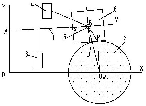
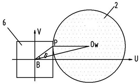
[0034] Example figure 1 As shown, the swing grinding device for special-shaped workpieces of the present invention includes a swing arm 1 that swings at point A, a grinding wheel 2, a lift drive mechanism 3, a swing drive mechanism 4, and a workpiece fixing shaft 5. The lift drive mechanism 3. Drive the swing arm 1 to rotate and swing around the fixed point A. The workpiece fixing shaft 5 is used to install the special-shaped workpiece 6 and is arranged at the front end of the swing arm 1. The rotary driving mechanism 4 drives the workpiece fixing shaft 5 to rotate , the workpiece fixing shaft 5 is concentric with the center of rotation of the special-shaped workpiece 6, while the lifting drive mechanism 3 drives the swing arm 1 to swing, the rotary drive mechanism 4 drives the workpiece fixing shaft 5 to make the special-shaped workpiece 6 rotate continuously, The grinding wheel 2 rotates and grinds the contour shape of the special-shaped workpiece 6 .

[0035] Preferably, t...


PUM


Abstract

The invention discloses a swing grinding device and method for a special-shaped workpiece. A lifting driving mechanism of the device drives a swing arm to swing around a point A in a rotary mode, a workpiece fixing shaft is arranged at the front end of the swing arm, a rotary driving mechanism drives the workpiece fixing shaft to rotate, and the lifting driving mechanism drives the swing arm to swing, meanwhile, the rotary driving mechanism drives the workpiece fixing shaft to enable the special-shaped workpiece to continuously rotate, and a grinding wheel rotates to grind the contour shape of the special-shaped workpiece. According to the method, the relation between the rotation angle of the special-shaped workpiece relative to the reference position and the lift height of the swing arm is calculated, a specific relational expression is obtained, and according to the specific relation, the lifting driving mechanism drives the swing arm to swing while the rotary driving mechanism drives the workpiece fixing shaft to enable the special-shaped workpiece to continuously rotate, and the contour shape of the special-shaped workpiece is machined through rotary grinding of the grinding wheel. According to the grinding device and method, through lifting driving of the swing arm and rotation driving of the workpiece, the grinding wheel rotates to grind the contour shape of the special-shaped workpiece according to the specific relation.

Description

technical field [0001] The invention relates to the technical field of machining, in particular to an oscillating grinding device and method for special-shaped workpieces. Background technique [0002] The grinding process of special-shaped workpieces is mainly represented by cams and polygonal workpieces. Most of the traditional machining processes use the method of profiling. The motor drives the grinding wheel to rotate, and then fixes the master model and the workpiece to be processed on the same rotation axis. , to realize the processing of the workpiece, the processing efficiency is low, and the precision is poor. [0003] The follow-up grinding technology originates from the processing of non-circular parts. When it is used in the processing of special-shaped workpieces, the circumferential feed of the grinding point can be realized through the cooperation of the rotation of the special-shaped workpiece and the linear reciprocating motion of the grinding wheel frame, ...

Claims


Application Information

Patent Timeline
IPC IPC(8): B24B19/12B24B19/08B24B41/06B24B47/16
Inventor 张满朝蔡留美
Owner SHANGHAI SUPORE INSTR
Learn More