Stepped multi-cutter continuous boring device and machining method for lathe

A stepped and lathe technology, applied in the direction of boring/drilling devices, metal processing equipment, manufacturing tools, etc., can solve the problems of poor processing accuracy, high processing cost, and increased cumulative error, so as to reduce processing cost and improve processing accuracy and efficiency

Inactive Publication Date: 2019-01-04
CHINA MCC20 GRP CORP
View PDF7 Cites 1 Cited by
  • Summary
  • Abstract
  • Description
  • Claims
  • Application Information

AI Technical Summary

Problems solved by technology

Generally, the diameter of the pin hole of the steel structure is relatively large, and the extension distance of the boring tool needs to be adjusted many times during the traditional lathe processing, resulting in low processing efficiency, which has become a processing problem that cannot be ignored.
[0003] The traditional processing method of steel structure pin holes is to use a boring machine for boring. One adjustment of the cutter head of the boring machine can only increase the hole diameter by about 2mm. To meet the design requirements of the pin hole diameter, it is often necessary to adjust the protrusion of the cutter head many times. The adjustment time Long, low processing efficiency, and the cumulative error increases due to multiple manual adjustments, resulting in poor processing accuracy
However, the new three-dimensional automatic boring equipment is often expensive, which is often unaffordable for most manufacturing companies, and the processing cost is high

Method used


Image

  • Stepped multi-cutter continuous boring device and machining method for lathe
  • Stepped multi-cutter continuous boring device and machining method for lathe

Examples


Embodiment Construction

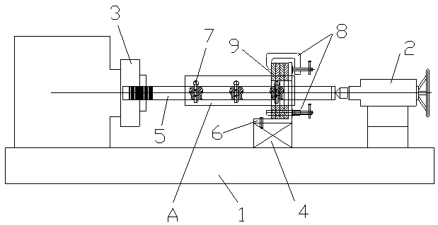
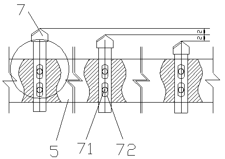
[0018] Example figure 1 and figure 2 As shown, the stepped multi-cutter continuous boring device for a lathe of the present invention includes a lathe frame 1, a lathe spindle power box 2, a lathe tailstock 3, a lathe slide box 4 and a main shaft 5, and the lathe spindle power box 2 and the lathe tailstock 3 are respectively arranged at the two ends of the lathe frame 1, and the main shaft 5 is arranged between the lathe spindle power box 2 and the lathe tailstock 3 and is driven to rotate by the lathe spindle power box 2. The lathe slide box 4 is arranged on the lathe frame 1 and moves along the main shaft 5. The device also includes a positioning plate 6 and a plurality of boring tools 7. The positioning plate 6 is arranged on the top surface of the lathe slide box 4. , the plurality of boring tools 7 are arranged at intervals on the main shaft 5 and the distance between the tool heads of the plurality of boring tools 7 is sequentially increased to the designed aperture of...


PUM


Abstract

The invention discloses a stepped multi-cutter continuous boring device and machining method for a lathe. A lathe spindle power box and a lathe tailstock of the stepped multi-cutter continuous boringdevice are arranged on a lathe rack, a spindle is arranged between the lathe spindle power box and the lathe tailstock, a lathe slide carriage box is arranged on the lathe rack, a positioning plate isarranged on the top face of the lathe slide carriage box, and a plurality of boring cutters are arranged on the spindle in a stepped mode. The stepped multi-cutter continuous boring machining methodcomprises the steps that the number of the boring cutters is determined according to the designed pin hole diameter of a machined piece, the boring cutters are mounted on the spindle, and the stretch-out difference of the boring cutters is set according to the cutting quantity of each time of boring till the stretch-out quantity of the boring cutter on the tail portion is matched with the designedpin hole diameter of the machined piece; and after the pin hole is precut in the machined piece, the machined piece is arranged on the positioning plate and fixed through a clamp, after the lathe isstarted, the lathe slide carriage box moves, thus the multiple boring cutters sequentially conduct boring machining on the precut pin hole in the machined piece till the designed hole diameter requirement is met. According to the stepped multi-cutter continuous boring device and machining method for the lathe, the pin hole diameter required by design is machined at a time, the machining cost is lowered, and the machining precision and efficiency are improved.

Description

technical field [0001] The invention relates to the field of mechanical processing, in particular to a stepped multi-cutter continuous boring device and a processing method for lathes. Background technique [0002] Pin connection is a common form of mechanical connection. In recent years, pin connection has been more and more widely used in building steel structures, long-span venue steel structures, and grid steel structures. Among them, the pin holes used to pass through the pin The machining accuracy requirements are high. Generally, the diameter of the pin hole of the steel structure is relatively large, and the extension distance of the boring tool needs to be adjusted many times during the traditional lathe processing, resulting in low processing efficiency, which has become a processing problem that cannot be ignored. [0003] The traditional processing method of steel structure pin holes is to use a boring machine for boring. One adjustment of the cutter head of the...

Claims


Application Information

Patent Timeline
Patent Type & Authority Applications(China)
IPC IPC(8): B23B43/02
CPCB23B43/02
Inventor 艾立文何月峰刘明路秦超高永强庞晶
Owner CHINA MCC20 GRP CORP
Why Eureka
Try Eureka