Nitrogen cylinder fixing device

A technology for fixing devices and nitrogen cylinders, which is applied in the field of nitrogen cylinders and can solve problems such as nitrogen cylinder shaking, low fixing efficiency, and nitrogen cylinder damage

Inactive Publication Date: 2021-04-16
宜春市富锐气体有限责任公司
View PDF16 Cites 4 Cited by
  • Summary
  • Abstract
  • Description
  • Claims
  • Application Information

AI Technical Summary

Problems solved by technology

However, the nitrogen bottle fixing device of the prior art is generally designed relatively simple, and often has the following disadvantages in use. First, when the nitrogen bottle is transported after being placed on the upper limit of the bottom plate, the nitrogen bottle is rigidly squeezed against the inner wall of the limit ring during transportation. Collision will easily cause damage to the nitrogen cylinder. When the second nitrogen cylinder is fixed in the limit ring, the fixing efficiency is low, and it is impossible to perform tight ring contact limit around the nitrogen cylinder. At the same time, the nitrogen cylinder needs to be buffered and protected. Finally, in the existing technology, after the chains at both ends of the front side wall of the limiting ring lock the nitrogen cylinder, the chain cannot directly lock the nitrogen cylinder, and can only limit the nitrogen cylinder, which is likely to cause nitrogen The bottle shakes or even tilts on the bottom plate

Method used


Image

  • Nitrogen cylinder fixing device
  • Nitrogen cylinder fixing device
  • Nitrogen cylinder fixing device

Examples


Embodiment Construction

[0032]The following will clearly and completely describe the technical solutions in the embodiments of the present invention with reference to the accompanying drawings in the embodiments of the present invention. Obviously, the described embodiments are only some, not all, embodiments of the present invention. Based on the embodiments of the present invention, all other embodiments obtained by persons of ordinary skill in the art without making creative efforts belong to the protection scope of the present invention.

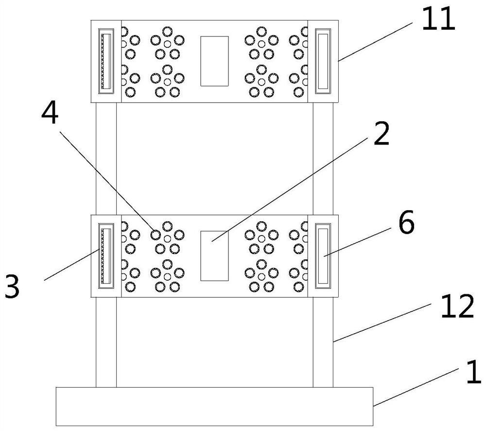
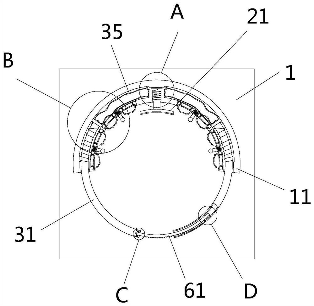
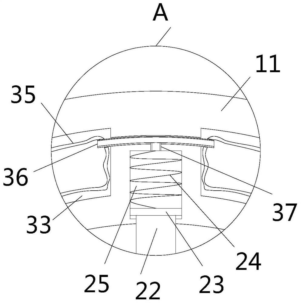
[0033] see Figure 1-8 , the present invention provides a technical solution: a nitrogen cylinder fixing device, including a chassis 1, two sets of fixing rings 11 and four sets of support columns 12 are arranged on the top of the chassis 1, the fixing rings 11 are semicircular, and every two supporting Columns 12 are respectively fixedly installed on the left and right sides of the bottom of a fixed ring 11, and the two supporting columns 12 at the bottom of t...


PUM


Abstract

The invention relates to the technical field of nitrogen cylinders, and discloses a nitrogen cylinder fixing device which comprises a base plate. Two sets of fixing rings and four sets of supporting columns are arranged at the top of the base plate, pressing devices are arranged in the middles of the inner concave faces of the front sides of the two fixing rings, and linkage limiting devices are arranged on the wall faces of the front sides of the two fixing rings. Each linkage limiting device comprises a limiting rod. According to the nitrogen cylinder fixing device, the fixing rings, the pressing devices and the linkage limiting devices are arranged, a nitrogen cylinder is fixedly stored, and a pressing plate is buffered and extruded through the outer wall of the rear side of the nitrogen cylinder, so that the pressing plate extrudes and injects air in a pressing groove cavity into two sets of linkage air bags; the two sets of pressurized linkage air bags extrude and push out the corresponding limiting rods through the sliding plates, finally, the outer wall of the nitrogen cylinder is annularly wrapped and limited through the four corresponding limiting rods in the upper set and the lower set, and the nitrogen cylinder is fixedly limited between the fixing rings and the limiting rods.

Description

technical field [0001] The invention relates to the technical field of nitrogen cylinders, in particular to a nitrogen cylinder fixing device. Background technique [0002] When the nitrogen cylinder is stored, it is generally placed on the bottom plate with a semicircular limit ring. The body of the nitrogen cylinder is limited in the annular groove of the limit ring, and then the chain is used to lock the nitrogen cylinder in the limit ring. The first purpose is to fix the nitrogen cylinder, and the second is to prevent the nitrogen cylinder from tilting or collapsing when it is stored on the bottom plate, so as to facilitate its transfer and transportation. However, the nitrogen bottle fixing device of the prior art is generally designed relatively simple, and often has the following disadvantages in use. First, when the nitrogen bottle is transported after being placed on the upper limit of the bottom plate, the nitrogen bottle is rigidly squeezed against the inner wall ...

Claims


Application Information

Patent Timeline
Patent Type & Authority Applications(China)
IPC IPC(8): B65D25/10B65D81/02
Inventor 王勇平
Owner 宜春市富锐气体有限责任公司
Why Eureka
Try Eureka