Multifunctional new energy battery box

A new energy and battery box technology, applied in the direction of secondary batteries, battery pack components, circuits, etc., can solve the problems that the battery box cannot give timely warnings, large safety risks, and the temperature rise of new energy batteries

Inactive Publication Date: 2021-04-16
叶和平
View PDF0 Cites 1 Cited by
  • Summary
  • Abstract
  • Description
  • Claims
  • Application Information

AI Technical Summary

Problems solved by technology

The design of the new energy battery box in the prior art is relatively simple, and often has the following practical disadvantages. First, when the new energy battery body works abnormally, the volume of the new energy battery body expands and generates a large amount of heat at the same time. New energy batteries are stored in the battery box. The battery box of the prior art cannot increase the ventilation and heat dissipation of the battery box in time, causing the temperature of the new energy battery in the battery box to rise sharply, resulting in a greater safety risk. Secondly, when the new After the abnormal operation of the energy battery increases the volume, the battery box of the prior art cannot give a timely warning to remind the user that the new energy battery body inside the battery box has produced an abnormal situation

Method used


Image

  • Multifunctional new energy battery box
  • Multifunctional new energy battery box
  • Multifunctional new energy battery box

Examples


Embodiment Construction

[0034] The following will clearly and completely describe the technical solutions in the embodiments of the present invention with reference to the accompanying drawings in the embodiments of the present invention. Obviously, the described embodiments are only some, not all, embodiments of the present invention. Based on the embodiments of the present invention, all other embodiments obtained by persons of ordinary skill in the art without making creative efforts belong to the protection scope of the present invention.

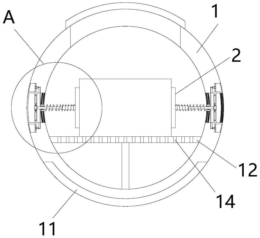
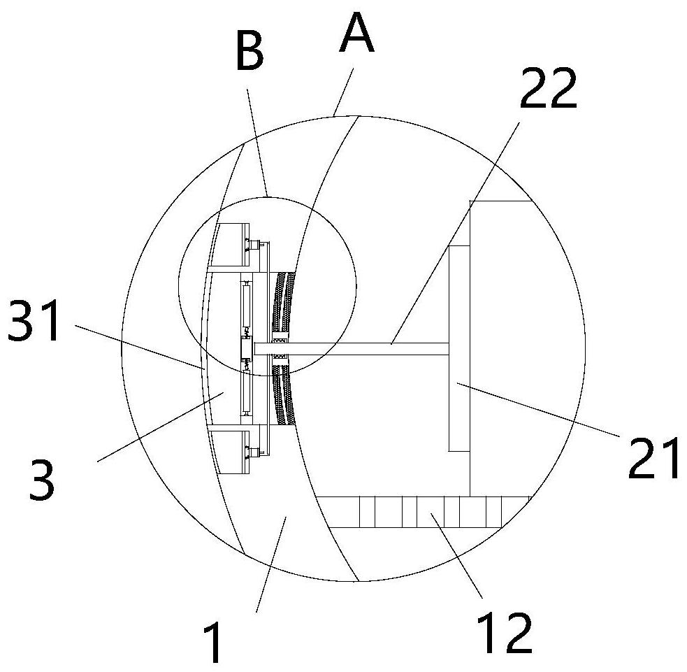
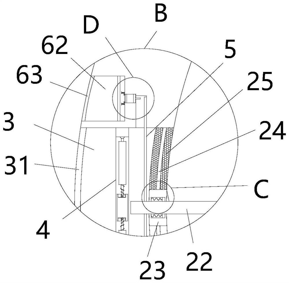
[0035] see Figure 1-11, the present invention provides a technical solution: a multifunctional new energy battery box, including a housing 1, the housing 1 is a hollow sphere, the top of the housing 1 is provided with an opening, and the opening is provided with a box cover, A circular support plate 12 is fixedly installed at the bottom of the cavity of the housing 1. The support plate 12 is provided with evenly distributed heat exhaust holes 14. The bottom o...


PUM


Abstract

The invention relates to the technical field of new energy batteries, and discloses a multifunctional new energy battery box. The battery box comprises a shell; four groups of heat dissipation holes distributed in an annular array are formed in the middle of the shell, four groups of fastening mechanisms distributed in an annular array are arranged in an inner cavity of a cavity of the shell, and the four groups of fastening mechanisms correspond to the corresponding heat dissipation holes respectively; and each fastening mechanism comprises a fastening plate, a fastening rod and a limiting block. According to the multifunctional new energy battery box, when the new energy battery body works abnormally and volume expansion and poor heat dissipation occur, the fastening rod is pushed through volume expansion of the new energy battery body to extrude and push the extrusion plate to one side in the heat dissipation hole cavity; the extrusion plates move to drive the heat dissipation plates distributed in the annular array to synchronously deflect towards one side in the heat dissipation hole cavity, so gaps between the heat dissipation plates distributed in the annular array are gradually enlarged, the ventilation and heat dissipation efficiency of the heat dissipation holes is improved, and the ventilation and heat dissipation efficiency of the new energy battery body is improved.

Description

technical field [0001] The invention relates to the technical field of new energy batteries, in particular to a multifunctional new energy battery box. Background technique [0002] The new energy battery is installed in the battery box of the car body. The new energy battery body will generate a certain amount of heat and temperature when it is working normally. Therefore, it is necessary to open corresponding cooling holes on the battery box for ventilation and heat dissipation. The design of the new energy battery box in the prior art is relatively simple, and often has the following practical disadvantages. First, when the new energy battery body works abnormally, the volume of the new energy battery body expands and generates a large amount of heat at the same time. New energy batteries are stored in the battery box. The battery box of the prior art cannot increase the ventilation and heat dissipation of the battery box in time, causing the temperature of the new energy...

Claims


Application Information

Patent Timeline
Patent Type & Authority Applications(China)
IPC IPC(8): H01M50/242H01M50/244H01M50/249H01M50/264H01M50/289H01M10/48H01M10/613H01M10/625H01M10/655H01M10/6554H01M10/6561
CPCY02E60/10
Inventor 叶和平
Owner 叶和平
Why Eureka
Try Eureka