Supercharge Your Innovation With Domain-Expert AI Agents!

Substrate conveyance robot, and method for teaching edge position of target body

一种边缘位置、示教方法的技术,应用在机械手、输送机物件、运输和包装等方向,能够解决难基板应用等问题

Active Publication Date: 2021-04-16
KAWASAKI JUKOGYO KK +1
View PDF9 Cites 0 Cited by
  • Summary
  • Abstract
  • Description
  • Claims
  • Application Information

AI Technical Summary

Problems solved by technology

In this way, in order to determine the position of the substrate in the plane perpendicular to the Z axis that is actually required, it is necessary to perform the previous stage of determining the position of the Z axis of the substrate, and the processing takes time.
In addition, in order to determine the Z-axis position of the substrate, the teaching jig for the simulated substrate needs to have a considerable thickness, and it is difficult to apply it to the actual substrate.

Method used


Image

  • Substrate conveyance robot, and method for teaching edge position of target body
  • Substrate conveyance robot, and method for teaching edge position of target body
  • Substrate conveyance robot, and method for teaching edge position of target body

Examples


Embodiment Construction

[0027] [Schematic structure of substrate transfer robot 1]

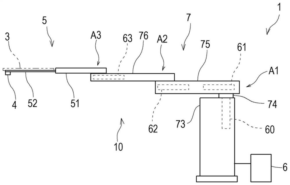
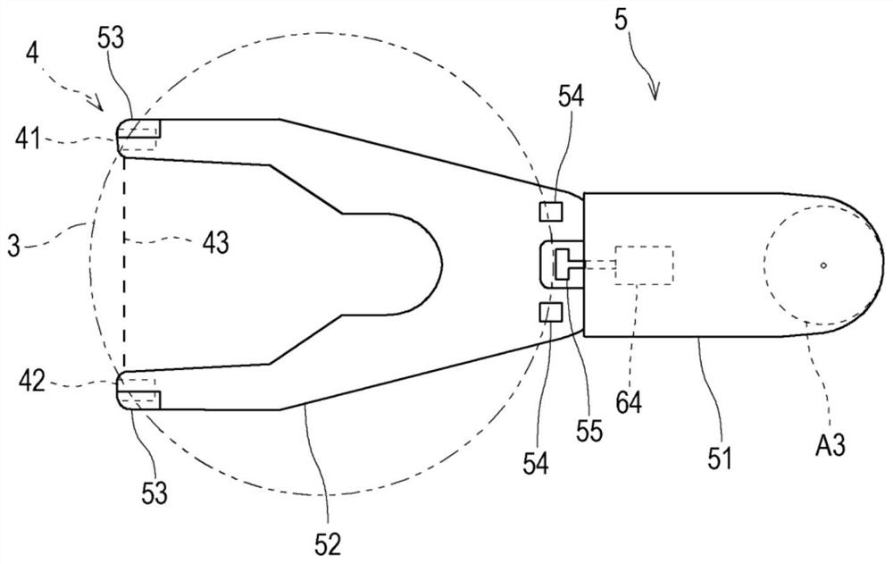
[0028] figure 1 It is a schematic side view of the substrate transfer robot 1 according to one embodiment of the present invention, figure 2 Yes figure 1 A plan view of the hand 5 included in the substrate transfer robot 1 shown. figure 1 as well as figure 2 The illustrated substrate transfer robot 1 includes a robot main body 10 and a controller 6 for controlling the operation of the robot main body 10 . The substrate transfer robot 1 is used to carry in (load) and carry out a substrate 3 from a substrate mounting section not shown. For example, the substrate transfer robot 1 may be provided in a system for transferring various substrates 3 such as EFEM (Equipment Front End Module), a sorter, and a substrate processing system.

[0029] [Structure of robot main body 10]

[0030] The robot main body 10 has: a base 73; a horizontal articulated robot arm (hereinafter referred to as "arm 7") supported on the base...


PUM


Abstract

This method for teaching the edge position of a target body involves: moving the optical axis of a photoelectric sensor to a prescribed initial position defined to be outside of the edge of a target body, which is arranged with the primary surface oriented horizontally, and above or below the target body; repeating a prescribed forward cycle of the optical axis until the edge of the target body is detected by the photoelectric sensor; and calculating and storing the position of a detected point of the target body edge on the basis of the orientation of the substrate conveying robot when the target body edge was detected by the photoelectric sensor. A movement cycle includes the series of movements of rising or lowering through the height level of the target body, moving forwards by a first movement amount in a horizontal scanning direction towards the target body, lowering or rising through the height level of the target body, and moving forwards by the first movement amount in the scanning direction.

Description

technical field [0001] The present invention relates to a technique for teaching the edge position of a substrate using a photoelectric sensor provided in a substrate holding hand in a substrate transfer robot. Background technique [0002] Conventionally, there is known a substrate transfer robot that includes a transmissive photoelectric sensor at the distal end of a substrate holding hand. This photoelectric sensor is used, for example, to detect the presence or absence of a substrate accommodated in each slot of the substrate carrier. In addition to this original purpose, the photoelectric sensor is also used for automatically teaching the positions of the substrate and its mounting portion to the substrate transfer robot. Patent Document 1 discloses such a technique. [0003] In Patent Document 1, it is disclosed that a teaching jig formed by vertically arranging a large circular plate portion having the same outer diameter as that of the semiconductor wafer and a sma...

Claims


Application Information

Patent Timeline
Patent Type & Authority Applications(China)
IPC IPC(8): H01L21/677
CPCH01L21/67259H01L21/681H01L21/68707B25J19/021B25J11/0095
Inventor 吉田哲也汤运欣
Owner KAWASAKI JUKOGYO KK
Features
  • R&D
  • Intellectual Property
  • Life Sciences
  • Materials
  • Tech Scout
  • Unparalleled Data Quality
  • Higher Quality Content
  • 60% Fewer Hallucinations
Learn More