Connecting device with two non-concentric shafts

A connecting device and connecting disc technology, which is applied in the direction of shaft coupling, rigid shaft coupling, contact operating mechanism, etc., can solve the problem of easy damage of the isolation reversing switch, inflexible rotation of the control handle, and inability to ensure the concentricity of the two shafts and other problems, to achieve the effect of smooth work, ingenious design and convenient installation

Inactive Publication Date: 2021-04-20
何贵庭
View PDF14 Cites 0 Cited by
  • Summary
  • Abstract
  • Description
  • Claims
  • Application Information

AI Technical Summary

Problems solved by technology

[0002] At present, the isolation reversing switch installed on the frame in the inner chamber of the explosion-proof switch is directly connected to the connection device of the operating handle installed outside the housing, and the operating handle installed outside the housing is rotated to drive the isolation reversing switch through the connecting device. Complete the opening and closing work; because the isolating reversing switch installed on the frame and the control handle installed outside the shell are subject to technological limitations, it is impossible to ensure that the two axes are concentric, so when the control handle is rotated, the connecting device is There will be a phenomenon of tension, which will make the installation of the movement difficult and difficult to adjust, the isolation and reversing switch will be easily damaged by external force, the frame will be deformed, the connecting device will not be easily connected, and the rotation of the control handle will not be flexible.

Method used


Image

  • Connecting device with two non-concentric shafts
  • Connecting device with two non-concentric shafts
  • Connecting device with two non-concentric shafts

Examples


Embodiment Construction

[0020]The technical solutions in the embodiments of the present invention will be described below, apparent, as described herein is merely embodiments of the invention, not all of the embodiments. Based on the embodiments of the present invention, there are all other embodiments obtained without making creative labor without making creative labor premises.

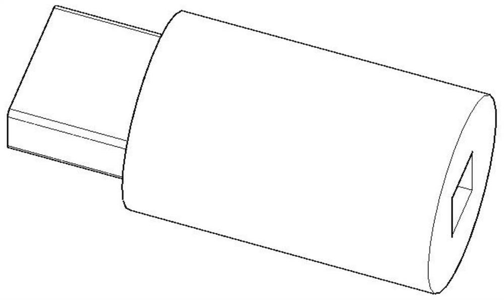
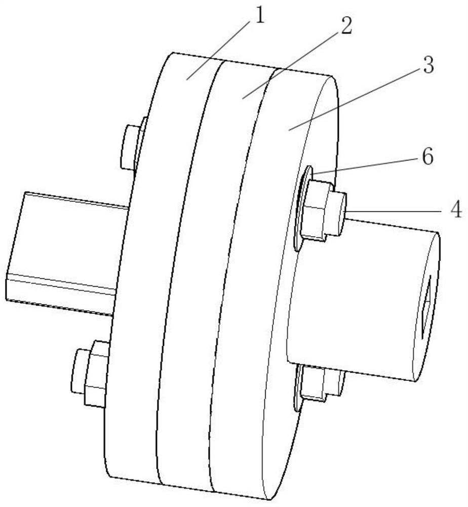
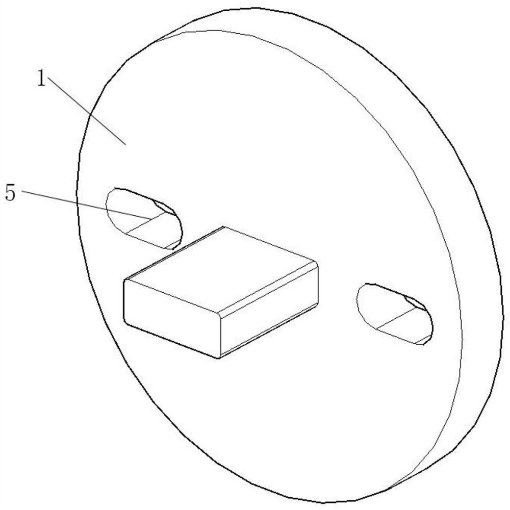
[0021]SeeFigure 1 to 5The present invention provides a two-axis differential attachment device for explosion-proof switch in the inner cavity mounted in the frame, an intermittent switching switch attached to the housing, including an isolated switching switch. The connection disk 1, the intermediate connection disk 2 and the manipulated hand put the connecting disk 3, the intermittent switching switch, the connection disk 1 and the manipulator, respectively, respectively on both sides of the intermediate connection disk 2, respectively, each side of the intermediate connection disk 2 Secure connector 4, the isolation switching swi...


PUM


Abstract

The invention relates to the field of mechanical connecting devices, and in particular relates to a connecting device with two non-concentric shafts. The connecting device comprises an isolation reversing switch connecting disc, a middle connecting disc and a control handle connecting disc, the isolation reversing switch connecting disc and the control handle connecting disc are located on the two sides of the middle connecting disc respectively, connecting pieces are fixed to the two sides of the middle connecting disc respectively, connecting piece movable holes are formed in the corresponding positions of the isolation reversing switch connecting disc and the control handle connecting disc, the connecting pieces can slide in the connecting piece movable holes, a part connected with an isolation reversing switch is further fixed to the isolation reversing switch connecting disc, and a part connected with a control handle is further fixed to the control handle connecting disc. Under the condition that the axis of the isolation reversing switch and the axis of the control handle are not concentric, the clamping phenomenon of the connecting device can be effectively relieved. The connecting device is ingenious in design, reasonable in structure, convenient to install, capable of well overcoming the defect that in the prior art, a connecting device is inflexible, and suitable for wide application and popularization.

Description

Technical field[0001]The present invention relates to the field of mechanical connecting devices, and more particularly to a two-axis differential attachment device.Background technique[0002]At present, the explosion-proof switch is mounted on the isolation and commutation switch on the rack and the manipulator hand mounted outside the housing is a straight joint, and the manipulating hand mounted outside the housing is driven by the connection device to drive the isolation switch, Completion of its division brake; because the isolation switching switch mounted on the rack is limited by the process of manipulating the hand, it is not possible to ensure that the two shafts are concentric, so when the rotating manipulation is handled, its connection means There will be a phenomenon, causing the movement of the movement to be difficult to adjust, the isolation and commutation switch is damaged by external force, the rack deformation, the connection device is not easy to connect, and th...

Claims


Application Information

Patent Timeline
Patent Type & Authority Applications(China)
IPC IPC(8): H01H3/54F16D1/033F16B19/02
Inventor 何贵庭
Owner 何贵庭
Why Eureka
Try Eureka