
Purifying system for high power output and low-temp tail gas discharge of IC engine

A purification system and high-power technology, which is applied in the fields of exhaust emission purification of automobiles, high power output of internal combustion engines, and low-temperature exhaust emission purification systems, can solve problems such as high cost, unsatisfactory purification effect, and no substantial contribution to the output power of internal combustion engines. Achieve the effects of low production cost, suppression of noise and vibration rate, and increase of effective output power

Inactive Publication Date: 2002-07-24
李树胜
View PDF0 Cites 19 Cited by
  • Summary
  • Abstract
  • Description
  • Claims
  • Application Information

AI Technical Summary

Problems solved by technology

[0013] To sum up, the existing various internal combustion engines, whether diesel engines or gasoline engines, have the following disadvantages in their exhaust emission purification devices: first, the purification effect is not ideal; second, the cost is high; third, there is no substantial contribution to improving the output power of the internal combustion engine

Method used


Image

  • Purifying system for high power output and low-temp tail gas discharge of IC engine
  • Purifying system for high power output and low-temp tail gas discharge of IC engine
  • Purifying system for high power output and low-temp tail gas discharge of IC engine

Examples


Embodiment 1

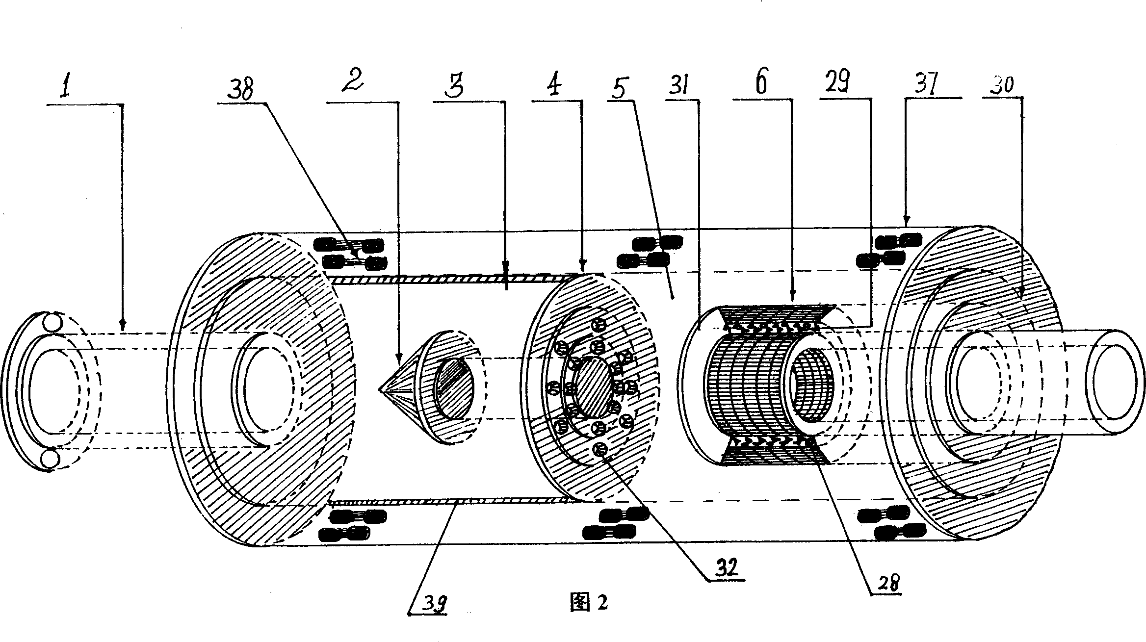
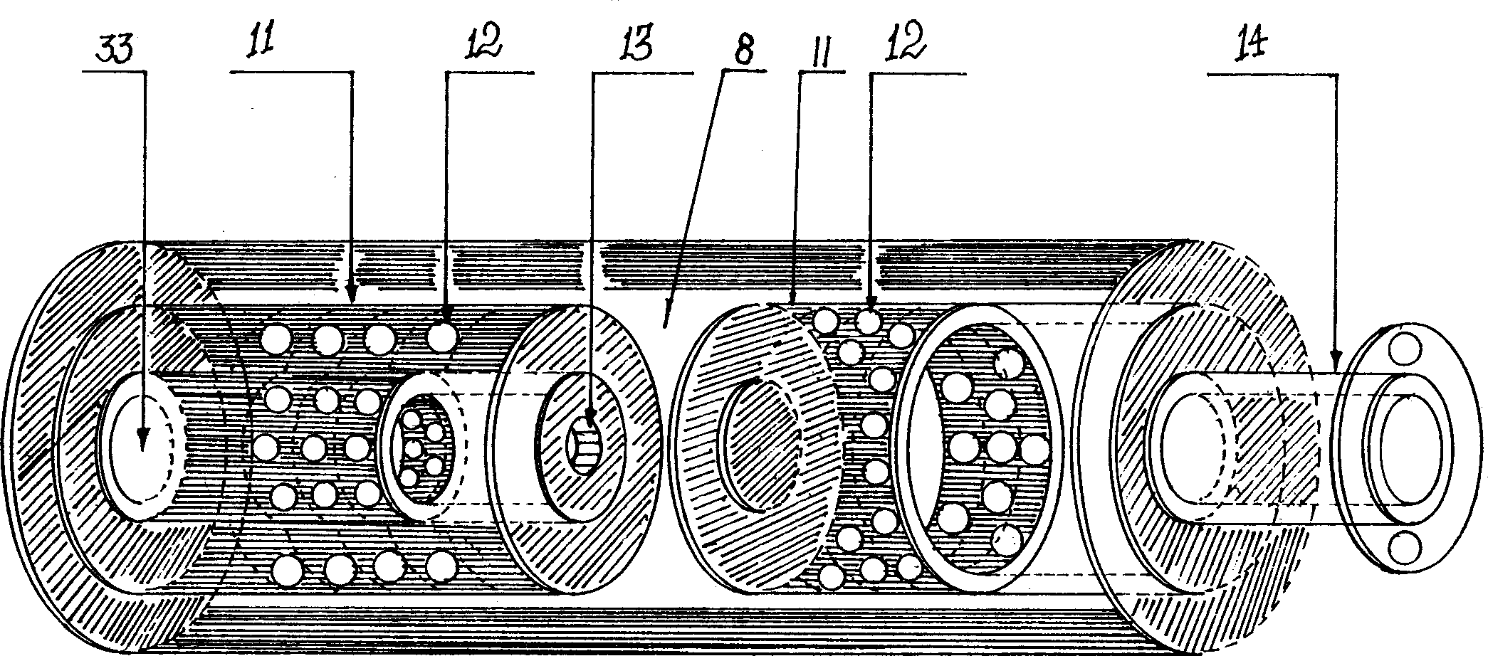
[0040] Example 1: Combining Figure 1 to Figure 5 , a gasoline engine internal combustion engine high power output, exhaust gas low temperature emission purification system, comprising a temperature raising and holding pressure vortex device, an air storage chamber 7, a filter, a muffler cooler 8, a decompression adsorber 9 and a muffler 10.

[0041] In Fig. 2, the temperature-raising and pressure-holding vortex device is composed of a vortex chamber 3, an airflow guide cone 2 and a restrictor plate 4. The airflow guide cone 2 is a conical, spherical or hemispherical metal body, facing the outlet of the engine exhaust manifold 1. The airflow guiding cone 2 is fixed at the center of the flow limiting plate 4, and the airflow guiding cone 2 is connected with the limiting plate 4 by electric welding, on the inner wall of the vortex chamber 3 or the limiting plate 4 or on the inner wall of the vortex chamber 3 and the limiting plate 4 A metal catalyst is fixed. Among them, the me...

Embodiment 2

[0052] Embodiment two: in conjunction with Fig. 2~4, Figure 6~7 , a diesel engine internal combustion engine high power output, exhaust gas low temperature emission purification system, comprising a temperature raising and pressure holding vortex device, a filter 5, a muffler cooler 8, a decompression adsorber 9 and an exhaust gas filter 10. Among them, such as Image 6 , Figure 7 As shown, the exhaust gas filter 10 includes a connecting pipe 21, a housing 23, a decompression buffer head 22, a primary filter element 24 and a secondary filter element 25, the decompression buffer head 22 is a conical or spherical metal body, the primary filter element 24 and the secondary filter element 25. The secondary filter element 25 is a paper air filter element, the connecting pipe 21 communicates with the inner cavity of the housing 23, the inner cavity of the housing 23 is provided with a decompression buffer head 22, the rear of the decompression buffer head 22 is provided with a pr...


PUM


Abstract

A system for higher power output and low-temp exhaust and cleaning of tail gas for IC engine is composed of temp-raising pressure-retaining swirler, filter, silencing cooler and vacuum adsorber. Saidswirler consists of swirl chamber, airflow guide cone, and flow limiting plate. Said silencing cooler comprises internal and external silencing cooling tubes with silencing holes. Said vacuum adsorber has internal and external metallic tubes with exhaust holes, activated carbon between two tubes and flow barrier. Its advantages are low cost, high output power, low noise and temp of exhausting tail gas, and tail gas cleaning function.

Description

technical field [0001] The invention relates to an internal combustion engine tail gas emission purification system, specifically a high power output, low temperature exhaust emission purification system of an internal combustion engine, which is suitable for use in equipment such as automobiles, trains, ships, etc., which use internal combustion engines as power devices, and is especially suitable for automobiles. Used for exhaust emission purification. Background technique [0002] Cars are one of the most important means of transportation invented by mankind. In a whole century, the number of cars in the world has reached more than 700 million. The main energy source of cars is oil. 50% of the world's oil is consumed by cars, and about 30% of the carbon dioxide (CO2) emissions of the world's entire transportation sector are Vehicle exhaust emissions, CO, CO2, HC and NO from vehicle exhaust emissions X It has caused a serious negative impact on the earth's atmospheric en...

Claims


Application Information

Patent Timeline
Patent Type & Authority Applications(China)
IPC IPC(8): B01D53/94F01N1/08F01N3/02F01N3/035F01N3/037F01N3/08F01N3/28
CPCF01N1/08F01N2370/40F01N3/035F01N3/0217B01D53/94F01N3/2885F01N3/037F01N3/2882F01N3/08F01N3/02
Inventor 李树胜
Owner 李树胜
Learn More