Turn-over device

The technology of a flipping device and a flipper is applied in the directions of measuring device, transportation and packaging, material analysis using radiation, etc. It can solve the problems of long working cycle, affecting the speed of the conveyor line and production rhythm, complex structure, etc. The effect of shortening the working cycle, stable and reliable work

Inactive Publication Date: 2008-07-02
NUCTECH CO LTD
View PDF0 Cites 19 Cited by
  • Summary
  • Abstract
  • Description
  • Claims
  • Application Information

AI Technical Summary

Problems solved by technology

The structure of the existing turning device includes a turning frame, a turning mechanism, a hydraulic or pneumatic pressing mechanism, a hydraulic or pneumatic pushing mechanism, etc., and the structure is relatively complicated.
The structure of this turning device is relatively complicated, and it can turn 180° at a time, and the working cycle is long, which affects the speed of the conveyor line and the production cycle.

Method used


Image

  • Turn-over device
  • Turn-over device
  • Turn-over device

Examples


Embodiment Construction

[0021] The following examples are used to illustrate the present invention, but are not intended to limit the scope of the present invention.

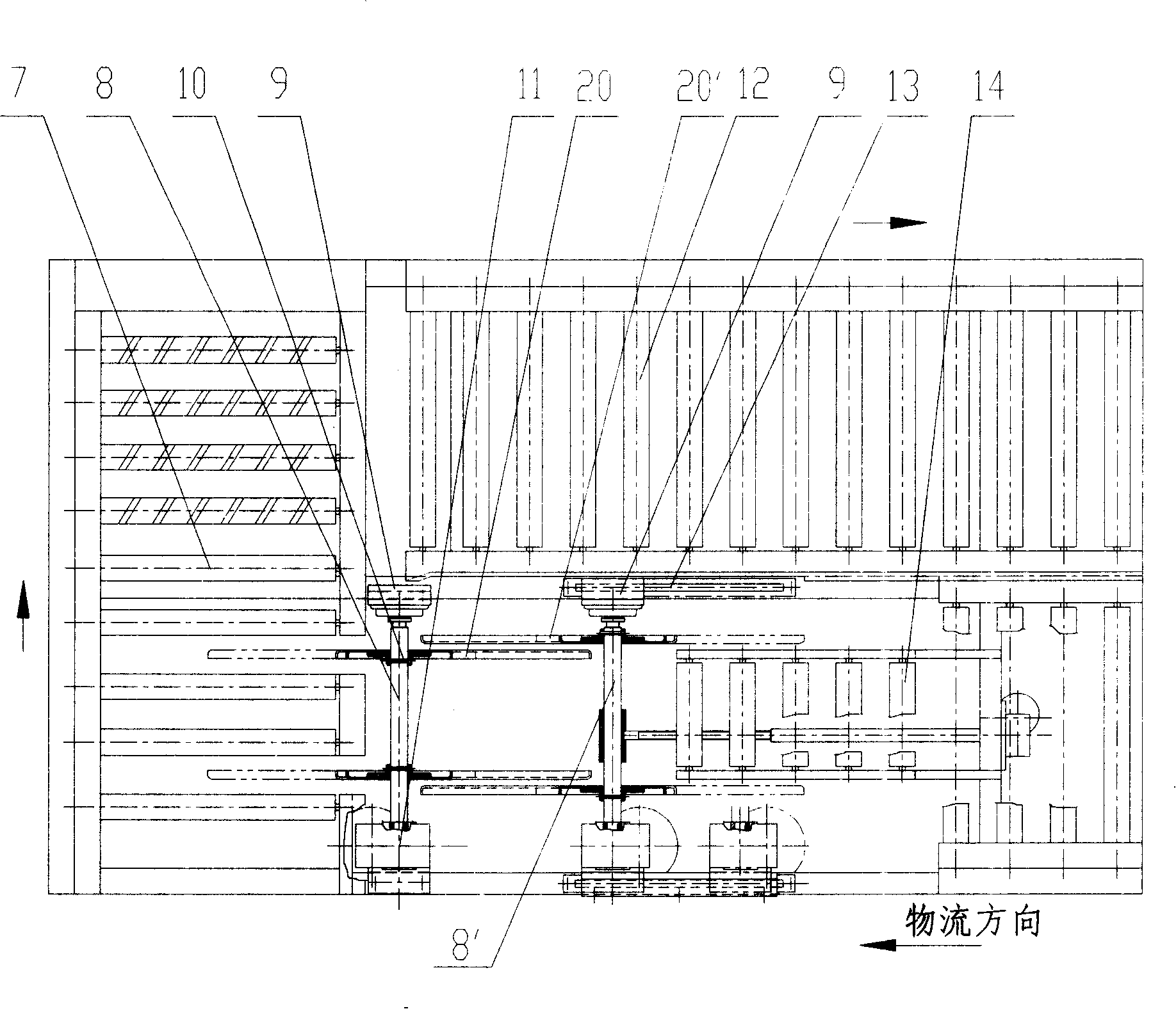
[0022] Such as figure 1 As shown, a conveyor line structure under electron beam irradiation includes a frame 1 , a forward conveyor roller set 14 , a turning conveyor roller set 7 and a reverse conveyor roller set 12 sequentially installed on the frame 1 . The overturning device of the present invention is installed on the frame 1 between the forward conveying roller group 14 and the turning conveying roller group 7 .

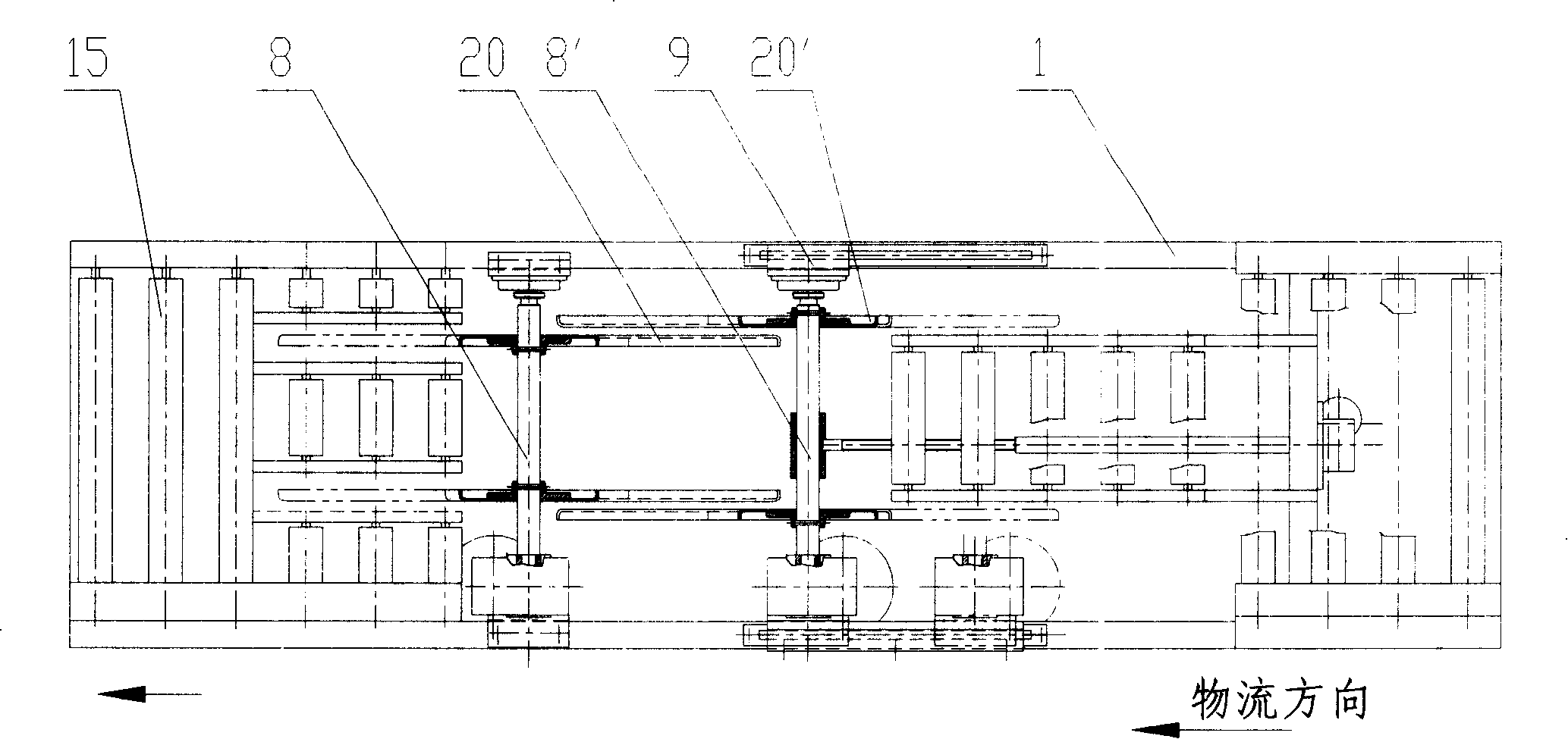
[0023] Such as figure 2 As shown, another conveying line structure under electron beam irradiation includes a frame 1 , a set of forward conveying rollers 14 and a set of straight output rollers 15 mounted on the frame 1 . The overturning device of the present invention is installed on the frame 1 between the forward conveying roller group 14 and the linear output roller group 15 .

[0024] Such as figure 1 with ...


PUM


Abstract

The invention provides an overturning device used on a transportation line under the irradiation of an electron beam which consists of two rotary shafts rotatably arranged in parallel on a frame and two overturning retarding motors fixed on the frame. The two ends of each rotary shaft are fixedly provided with a pair of tumblers. The two pairs of tumblers on two rotary shafts have same structures which consist of a middle body and four overturning arms fixed that is combined with the middle body to be a whole or fixed on the middle body and the axle wires of the four overturning arms are all uniformly arranged on the tangent direction of a same circumference. The corresponding overturning arms of the tumblers on the two rotary shafts are arranged mutually parallel and overlapped. The invention has simple structure, can adopt 90 DEG overturning for twice, shorts one time of the working period and improves the working efficiency and simultaneously ensures reliable transportation.

Description

technical field [0001] The invention relates to an overturning device, in particular to an overturning device used on a conveying line under electron beam irradiation. Background technique [0002] At present, the commonly used security inspection system adopts the form of electron beam irradiation. When electron beams are used to irradiate items with packaging boxes, due to the weak penetrating power of electron beams, the irradiation dose of single-sided irradiation on the upper and lower sides of the object is very uneven. In order to improve its uniformity, it is often necessary to irradiate the object both sides. At this time, it is necessary to turn the packing box 180° after irradiating one side on the conveyor line, and irradiate the other side of the object. The structure of the existing turning device comprises a turning frame, a turning mechanism, a hydraulic or pneumatic pressing mechanism, a hydraulic or pneumatic pushing mechanism, etc., and the structure is ...

Claims


Application Information

Patent Timeline
Patent Type & Authority Applications(China)
IPC IPC(8): B65G47/24G01N23/04G01N23/08
Inventor 刘不腐刘新民刘以农苗齐田
Owner NUCTECH CO LTD
Why Eureka
Try Eureka