Check patentability & draft patents in minutes with Patsnap Eureka AI!

Noise reduction method

A noise and low temperature technology, applied in the direction of gas cycle refrigerators, refrigeration safety arrangements, refrigerators, etc.

Active Publication Date: 2021-04-20
OXFORD INSTR NANOTECH TOOLS
View PDF17 Cites 0 Cited by
  • Summary
  • Abstract
  • Description
  • Claims
  • Application Information

AI Technical Summary

Problems solved by technology

Microphony in the lab wiring generated by these vibrations can couple into the lab wiring to which sensitive samples are connected, causing electrical noise in the measurement circuit

Method used


Image

  • Noise reduction method
  • Noise reduction method
  • Noise reduction method

Examples


Embodiment Construction

[0043] An example of a noise reduction method is now described, along with a description of an example cryogenic cooling system including an example frequency regulator.

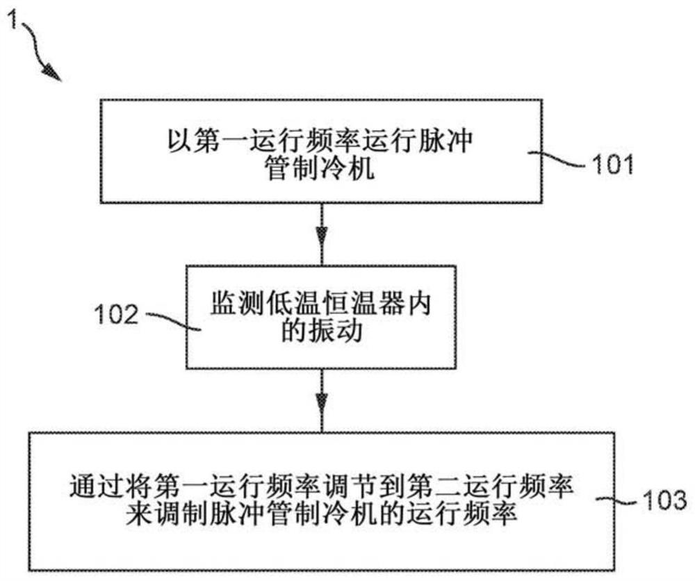
[0044] now refer to figure 1 with figure 2 , figure 1 Reference numeral 1 in generally shows the process of the first example noise reduction method, and figure 2 An exemplary cryogenic cooling system is shown generally at 10 in .

[0045] In the cryogenic cooling system 10, a pulse tube refrigerator (PTR) 12 is coupled to a cryostat 14, typically mounted in a support frame (not shown). An accelerometer 16 is in contact with the cryostat and is connected to a controller 18 to which the accelerometer outputs data. The accelerometer and controller form the frequency regulator.

[0046] In step 101, the PTR 12 is operated at a first operating frequency. This is accomplished by operating a rotary valve (not shown) in the PTR at a first operating frequency. Additionally, PTRs typically have external comp...


PUM


Abstract

There is provided a method of reducing noise in a cryogenic cooling system associated with a mechanical refrigerator forming part of said cooling system. The method comprises: monitoring vibrations in the cooling system during operation of the mechanical refrigerator; and modulating an operating frequency of the mechanical refrigerator based on the monitored vibrations so as to reduce the amplitude of said vibrations. This allows noise within the cooling system to be reduced.

Description

technical field [0001] The present invention relates to noise reduction in cryogenic cooling systems, and is intended to reduce the noise associated with mechanical refrigerators coupled to such cooling systems. Background technique [0002] Many experiments and processes have been performed at cryogenic temperatures, for example at temperatures below 77 Kelvin (K) or at temperatures around or below 4K. In the past, cryogenic fluids such as liquid nitrogen and liquid helium have been used to achieve these temperatures. These fluids are usually produced in dedicated liquefaction plants (characterized by powerful mechanical compressors and expansion stages) and then transported (in liquid form) to the experimental area where the cooling power (also called cooling capacity, of the fluid) is consumed in the experimental area. That is, the ability of the fluid to provide cooling). Thus, there is a separation between cold source "production" and "consumption", and the associated...

Claims


Application Information

Patent Timeline
Patent Type & Authority Applications(China)
IPC IPC(8): F25B9/14
CPCF25B9/145F25B2500/12F25B2500/13F25B2309/1427F25B9/14F25B49/022F25B49/025F25B49/027F25D16/00F25D23/003F25D29/001F25B2600/0253
Inventor 安东尼·J·马修斯马克·巴顿杰里米·怀特
Owner OXFORD INSTR NANOTECH TOOLS
Features
  • R&D
  • Intellectual Property
  • Life Sciences
  • Materials
  • Tech Scout
  • Unparalleled Data Quality
  • Higher Quality Content
  • 60% Fewer Hallucinations
Learn More