Eureka AIR delivers breakthrough ideas for toughest innovation challenges, trusted by R&D personnel around the world.

Variable-gradient load mechanism

A load and gradient technology, applied in the direction of human manipulation, control start method, etc., can solve the problems of low yield rate, limited spring manufacturing precision, and inability to eliminate, so as to reduce the manipulation burden and improve the operation precision.

Pending Publication Date: 2021-04-23
SHENYANG AIRCRAFT DESIGN INST AVIATION IND CORP OF CHINA
View PDF0 Cites 0 Cited by
  • Summary
  • Abstract
  • Description
  • Claims
  • Application Information

AI Technical Summary

Problems solved by technology

[0006] c) The existing variable gradient load mechanism compresses the small spring when the displacement is small, and compresses the large spring when the displacement is large after the mechanical limit, but this load mechanism is limited by the manufacturing accuracy of the spring. Inflection point) tends to produce a force gradient (that is, the force at the maximum stroke of the small spring is less than the preload force of the large spring, and the force of the load mechanism increases while the displacement continues to be compressed). To manufacture a load mechanism that meets the requirements, it is necessary to select a spring Thus affecting the production efficiency, the yield rate is not high, and the force difference can only be reduced but cannot be eliminated

Method used


Image

  • Variable-gradient load mechanism
  • Variable-gradient load mechanism
  • Variable-gradient load mechanism

Examples


Embodiment Construction

[0032]In order to make the objects, technical solutions, and advantages of the present application, the technical solutions in the present application embodiment will be described in more detail below in connection with the drawings in the present application embodiment.

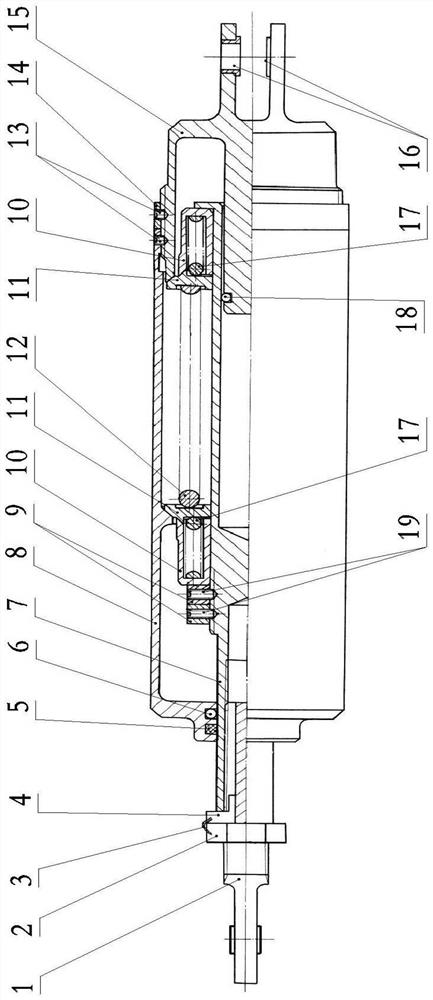
[0033]Such asFigure 1 to 9 As shown, the gradient load mechanism provided herein mainly includes: the earrings 1, the rear housing 15, the core rod 7, the bushing 10, the first spring 17, the second spring 12, and the main casing 8, and the like. The core rod 7 is disposed between the earrings 1 and the rear housing 15, the core rod 7 relative to the earrings 1, and the other end can be moved relative to the rear housing 15.

[0034]In one embodiment of the present application, the mandrel 7 and the earrings 1 are limited by the nut 2 that is screwed into the earrings 1. When installing, the earrings 1 is screwed into the thread of the core rod 7, and at the same time, with the limit key 4, the slot of the limit slot of...


PUM


Abstract

The invention provides a variable-gradient load mechanism. The variable-gradient load mechanism comprises an earring joint; a rear housing; and a core rod which is arranged between the earring joint and the rear shell, one end of the core rod and the earring joint are relatively limited, and the other end of the core rod can move relative to the rear shell; bushings with first springs are arranged on the two sides, close to the earring connector and the rear shell, of the core rod respectively, check rings are arranged at ports of the bushings, a second spring is arranged between the two bushings, the elastic force of the second spring is larger than that of the first spring, and the bushings are limited by limiting mechanisms arranged on the corresponding sides of the core rod; wherein the core rod and the rear shell are partially sleeved with the main shell, a cavity of the lining is formed between the main shell and the core rod, and the main shell and the rear shell are relatively fixed. The variable-gradient load mechanism has a large force gradient during small displacement and a small rod force gradient during large displacement control, the operation precision during small displacement is improved, and the control burden of a driver during large displacement is reduced.

Description

Technical field[0001]The present application belongs to the field of aircraft operation control technology, and more particularly to a gradient load mechanism.Background technique[0002]The load mechanism is a mechanical device that provides a manipulating force in the aircraft manipulation system. When the driver is pulling / pressing the rod or the pedal, the driver will stretch or compress the load mechanism, and the spring within the mechanism is compressed to provide the driver spring against the driver.[0003]The load mechanism used in the existing aircraft manipulation system has the following shortcomings or lack of:[0004]a) Small single gradient load mechanism is light in the small displacement, and the manipulation operation is easily interfered, and cannot be accurately manipulated;[0005]b) The larger single gradient load mechanism is heavy, and the driver manipulates the burden;[0006]c) The existing viable gradient load mechanism compresses the small spring in the small di...

Claims


Application Information

Patent Timeline
Patent Type & Authority Applications(China)
IPC IPC(8): B64C13/04
Inventor 孙永环赵冬柏徐文良庞志军张剑
Owner SHENYANG AIRCRAFT DESIGN INST AVIATION IND CORP OF CHINA
Why Eureka
Eureka Blog
Learn More