
Traffic monitoring camera device

A camera device and traffic monitoring technology, which is applied in image communication, television, supporting machines, etc., can solve the problems of unable to monitor the camera to remove fog and dust, unable to adjust the position, and monitor dead angles.

Pending Publication Date: 2021-04-23
HUAIYIN INSTITUTE OF TECHNOLOGY
View PDF7 Cites 0 Cited by
  • Summary
  • Abstract
  • Description
  • Claims
  • Application Information

AI Technical Summary

Problems solved by technology

[0004] Purpose of the invention: Aiming at the deficiencies in the prior art, the present invention provides a traffic monitoring camera device, which solves the problem that the existing monitoring device cannot adjust the position, resulting in monitoring dead angles and the inability to remove the monitoring camera. fog dust problem

Method used


Image

  • Traffic monitoring camera device
  • Traffic monitoring camera device
  • Traffic monitoring camera device

Examples


Embodiment Construction

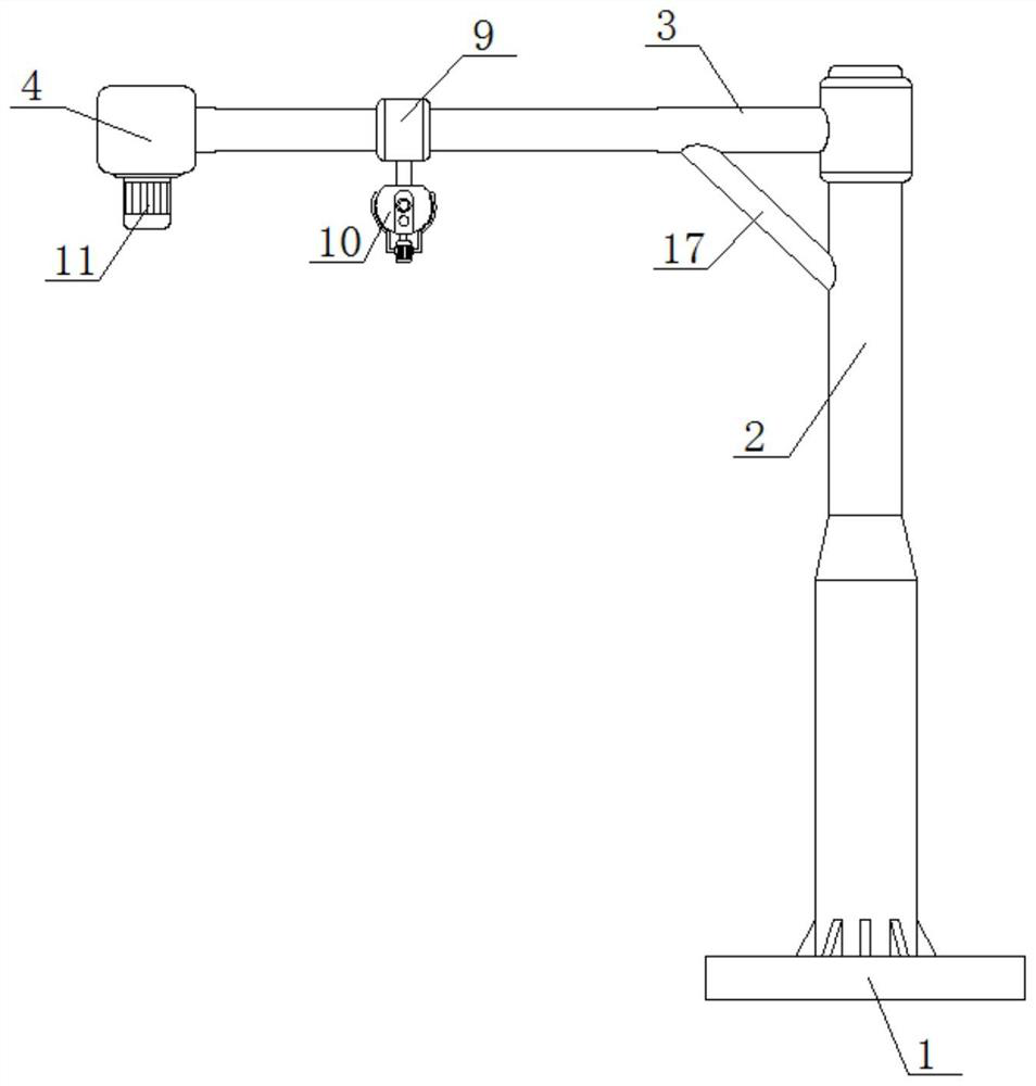
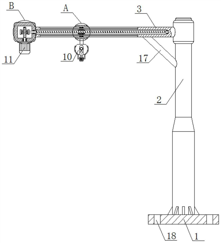
[0023] Such as Figure 1 to Figure 5 As shown, the traffic monitoring camera device of the present invention includes a monitoring component, a supporting component, a driving mechanism and a moving component.

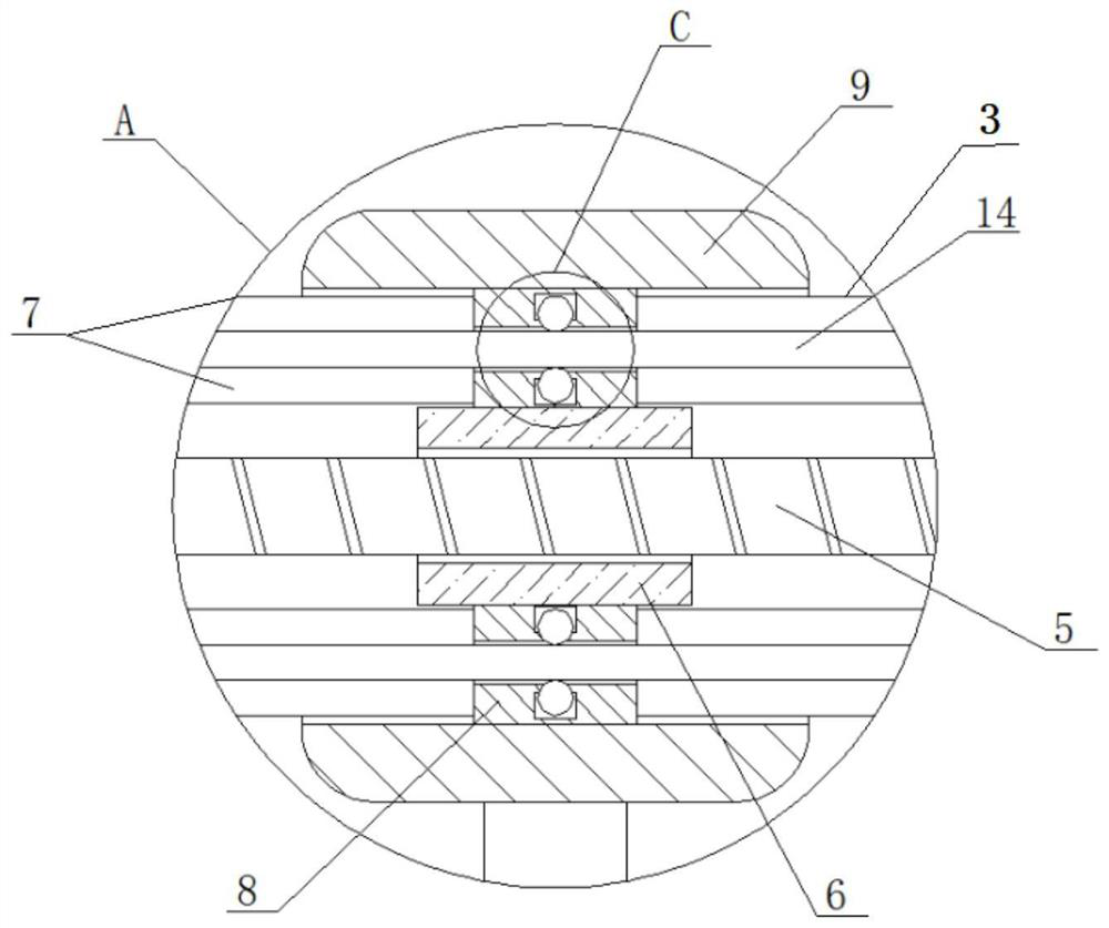
[0024] The monitoring component includes a monitoring camera main body 10 and a fog and dust removal device. The support assembly includes a base 1, the upper end of the base 1 is fixedly connected with a support rod 2, and the wall of the support rod 2 near the upper end is fixedly connected with a cross bar 3. The cross bar 3 is hollow, and the end of the cross bar 3 away from the support bar 2 is fixedly connected with a fixed box 4 . A driving mechanism and a moving assembly are installed in the fixed box 4 , and the moving assembly includes a screw rod 5 , a threaded sleeve 6 and a moving sleeve 9 . The specific connection relationship between the mobile component and the drive mechanism is:

[0025] The output end of the driving mechanism is connected with a s...


PUM


Abstract

The invention discloses a traffic monitoring camera device. The camera device comprises a monitoring assembly, a supporting assembly, a driving mechanism and a moving assembly. The monitoring assembly is provided with a camera body and a demisting and dedusting device, and the demisting and dedusting device is provided with a motor and a cleaning rod. The supporting assembly comprises a cross rod and a supporting rod, and a channel is formed in the cross rod; the moving assembly comprises a screw rod, a threaded sleeve and a moving sleeve; the screw rod is located at the output end of the driving mechanism, the threaded sleeve is driven by the screw rod to move, and the movable sleeve drives the monitoring camera body to move on the cross rod through the threaded sleeve for monitoring. A moving block is arranged on the threaded sleeve and located in the channel. And the threaded sleeve drives the movable sleeve to move on the cross rod through the movable block. The traffic monitoring camera device carries out shooting monitoring on a shooting object in an omnibearing and dead-angle-free mode, demisting and dedusting are carried out on the camera body through the demisting and dedusting device, and the problems that an existing monitoring device has monitoring dead angles and cannot be cleaned are solved.

Description

technical field [0001] The invention relates to monitoring camera equipment, in particular to a traffic monitoring camera device. Background technique [0002] Urban road monitoring system plays an important role in public security prevention and control. In order to improve traffic congestion, cities are gradually promoting the implementation of real-time traffic condition image monitoring system plans at important traffic crossings, that is, installing a set of The intelligent road monitoring system uploads the road traffic conditions to the road monitoring command center in real time through the image transmission channel, so that the personnel on duty at the center can keep abreast of the road conditions in each area. [0003] However, although the existing monitoring device can adjust the angle, the position cannot be adjusted, and it cannot remove fog and dust. When the subject is blocked by an occluder, the subject cannot be monitored by adjusting the angle, there is...

Claims


Application Information

Patent Timeline
Patent Type & Authority Applications(China)
IPC IPC(8): H04N7/18H04N5/232F16M11/18F16M11/04H04N5/225B08B1/04
CPCH04N7/185F16M11/18F16M11/045H04N23/50H04N23/695B08B1/32
Inventor 陈鑫将周桂良吴鼎新徐悦施荣成赵甜甜覃稍毛丽娜夏晶晶
Owner HUAIYIN INSTITUTE OF TECHNOLOGY
Learn More