Locatable punching device with regard to ceiling and used for indoor decoration
A technology for interior decoration and drilling devices, which is applied in positioning devices, feeding devices, boring/drilling, etc., and can solve problems such as low efficiency and labor-intensive
- Summary
- Abstract
- Description
- Claims
- Application Information
AI Technical Summary
Problems solved by technology
Method used
Image
Examples
Embodiment 1
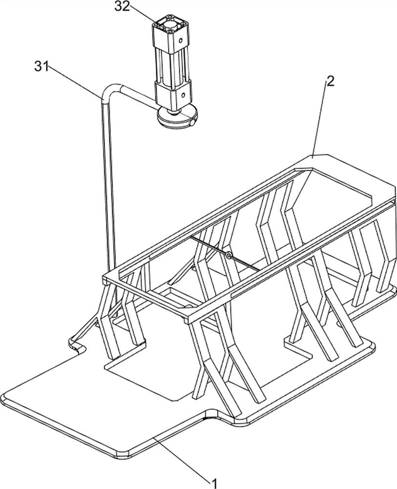
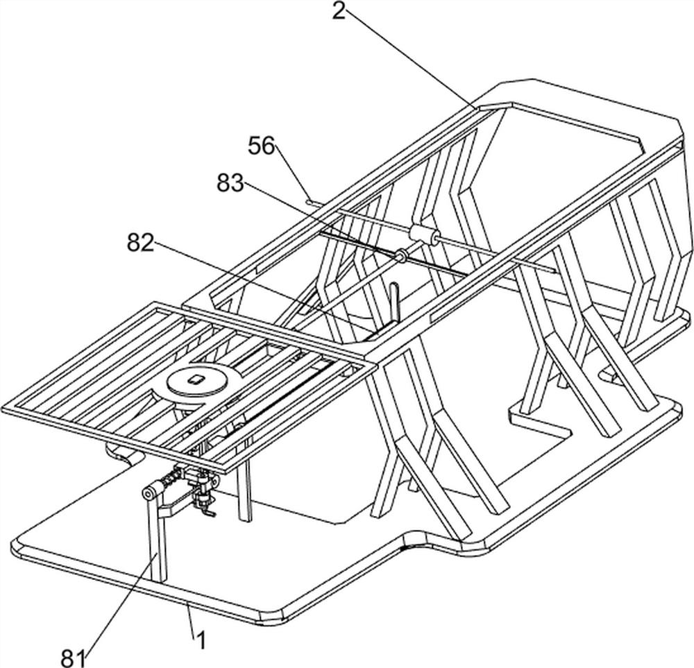
[0066] A perforation device for upholstery that can be positioned against the ceiling, such as figure 1 As shown, it includes a base 1, a support frame 2, a press-down mechanism 3, a punching mechanism 4 and a feeding mechanism 5, a support frame 2 is provided on the rear side of the upper part of the base 1, and a press-down mechanism 3 is provided on the left side of the upper part of the base 1. The lower side of the pressing mechanism 3 is provided with a punching mechanism 4, and the upper side of the support frame 2 is provided with a feeding mechanism 5.
[0067] When people need to punch holes in the ceiling, they first put the ceiling on the support frame 2, then start the pressing mechanism 3, and the pressing mechanism 3 drives the punching mechanism 4 to reciprocate up and down, which realizes the operation of punching the ceiling , The punching mechanism 4 reciprocates up and down to drive the feeding mechanism 5 to move, which realizes the effect of feeding, and th...
Embodiment 2
[0069] On the basis of Example 1, such as Figure 2-5 As shown, the pressing mechanism 3 includes a bracket 31 and a cylinder 32 , the upper left side of the base 1 is provided with a bracket 31 , and the cylinder 32 is installed on the bracket 31 .
[0070] When people need to punch holes, start the cylinder 32, and the telescopic rod of the cylinder 32 drives the punching mechanism 4 to reciprocate up and down, which realizes the operation of pressing the punching mechanism 4 down, and closes the cylinder 32 when not needing punching.
[0071] Punching mechanism 4 comprises fixed block 41, the first fixed rod 42 and electric drill 43, is connected with fixed block 41 on the telescoping rod of cylinder 32, and electric drill 43 is installed in fixed block 41 inboard, and fixed block 41 left and right sides are all provided with the first. A fixed rod 42.
[0072] The telescopic rod of the cylinder 32 drives the fixed block 41 to reciprocate up and down, thereby driving the e...
Embodiment 3
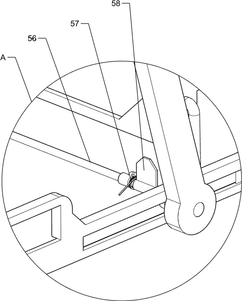
[0076] On the basis of Example 2, such as Figure 6-10 As shown, a clamping mechanism 6 is also included, and the clamping mechanism 6 includes a third fixed rod 61, a wedge rod 62, a sliding rod 63, a first spring 64, a pressing plate 65 and a telescopic rod 66, and the brackets 31 on the left and right sides A third fixed rod 61 is arranged on the top, and a wedge-shaped rod 62 is slidably provided on the third fixed rod 61. The wedge-shaped rod 62 cooperates with the rotating rod 53, and a telescopic rod 66 is arranged between the wedge-shaped rod 62 and the third fixed rod 61. A sliding bar 63 is slidably arranged on the fixed frame 52 , and a pressing plate 65 is arranged inside the sliding bar 63 , and a first spring 64 is connected between the pressing plate 65 and the fixing frame 52 .
[0077] When the rotating rod 53 swings downward, the rotating rod 53 contacts the wedge-shaped rod 62, thereby driving the wedge-shaped rod 62 to move downward, the telescopic rod 66 i...
PUM
 Abstract
Description
Claims
Application Information
 - R&D
- Intellectual Property
- Life Sciences
- Materials
- Tech Scout
- Unparalleled Data Quality
- Higher Quality Content
- 60% Fewer Hallucinations
Browse by: Latest US Patents, China's latest patents, Technical Efficacy Thesaurus, Application Domain, Technology Topic, Popular Technical Reports.
© 2025 PatSnap. All rights reserved.Legal|Privacy policy|Modern Slavery Act Transparency Statement|Sitemap|About US| Contact US: help@patsnap.com


