
Novel civil construction supporting structure

A technology of civil architecture and supporting structures, which is applied in the direction of building construction, construction, and on-site preparation of building components. It can solve problems such as a large amount of preparation time, reduced construction efficiency, and troublesome operations for fixing support columns.

Inactive Publication Date: 2021-04-27
ZHENGZHOU RAILWAY VOCATIONAL & TECH COLLEGE
View PDF5 Cites 0 Cited by
  • Summary
  • Abstract
  • Description
  • Claims
  • Application Information

AI Technical Summary

Problems solved by technology

[0002] Civil construction is a general term for the science and technology of building various engineering facilities; it refers to the materials, equipment and technical activities such as survey, design, construction, maintenance and repair; it also refers to the object of engineering construction, that is, the construction on the ground Or underground, on land or in water, various engineering facilities that directly or indirectly serve human life, production, military affairs, and scientific research. During the construction process, the building structure needs to be supported to make the concrete solidify, so a support structure is required; but Existing support structures generally use support columns of a specified height to support the concrete structure, which leads to splicing or shortening when supporting other building structures, which requires a lot of preparation time in the early stage of support, which reduces construction efficiency. It also needs to be fixed between them. If there is no splicing device, the fixing operation between the supporting columns will be too troublesome, which will also reduce the efficiency of splicing

Method used


Image

  • Novel civil construction supporting structure
  • Novel civil construction supporting structure
  • Novel civil construction supporting structure

Examples


Embodiment Construction

[0021] The technical solutions of the present invention will be clearly and completely described below in conjunction with the embodiments. Apparently, the described embodiments are only some of the embodiments of the present invention, not all of them. Based on the embodiments of the present invention, all other embodiments obtained by persons of ordinary skill in the art without creative efforts fall within the protection scope of the present invention.

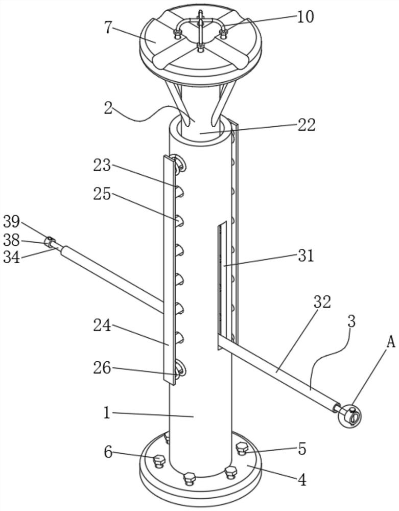
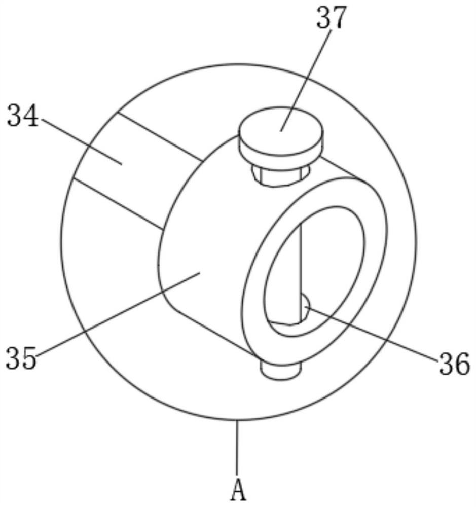
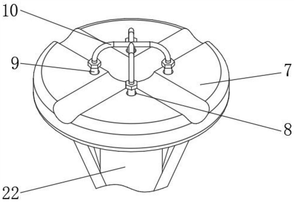
[0022] like Figure 1-4 As shown, a new civil construction support structure includes a support sleeve 1, a lifting adjustment assembly 2 and a splicing assembly 3. The lifting adjustment assembly 2 is fixed on the inner wall of one side of the support sleeve 1, and the outer wall of one side of the support sleeve 1 The splicing assembly 3 is fixed on it; the lifting adjustment assembly 2 includes a cylinder 21, a lifting support column 22, a second guide hole 23, a connecting plate 24, a limit rod 25, a first spring 26 and...


PUM


Abstract

The invention discloses a novel civil construction supporting structure. The supporting structure comprises a supporting sleeve, a lifting adjusting assembly and a splicing assembly, wherein the lifting adjusting assembly is fixed to the inner wall of one side of the supporting sleeve, the splicing assembly is fixed to the outer wall of one side of the supporting sleeve, the lifting adjusting assembly comprises an air cylinder, a lifting supporting column, second guide holes, connecting plates, limiting rods, first springs and limiting grooves, the inner wall of one side of the supporting sleeve is fixedly sleeved with the lifting supporting column, and the air cylinder is embedded in the inner wall of the bottom end of the supporting sleeve. According to the supporting structure, by adopting a lifting adjusting device, the height of the supporting column can be adjusted, so that the supporting column can adapt to the heights of most buildings, the buildings can be supported, concrete solidification is ensured, the earlier-stage preparation time can be shortened, the working period can be shortened, and the construction efficiency can be improved; and a splicing device is further adopted, the supporting columns can be spliced and fixed through splicing operation, and the splicing efficiency is improved.

Description

technical field [0001] The invention relates to the field of building support equipment, in particular to a novel civil building support structure. Background technique [0002] Civil construction is a general term for the science and technology of building various engineering facilities; it refers to the materials, equipment and technical activities such as survey, design, construction, maintenance and repair; it also refers to the object of engineering construction, that is, the construction on the ground Or underground, on land or in water, various engineering facilities that directly or indirectly serve human life, production, military affairs, and scientific research. During the construction process, the building structure needs to be supported to make the concrete solidify, so a support structure is required; but Existing support structures generally use support columns of a specified height to support the concrete structure, which leads to splicing or shortening when ...

Claims


Application Information

Patent Timeline
Patent Type & Authority Applications(China)
IPC IPC(8): E04G25/04E04G25/06
CPCE04G25/04E04G25/061E04G2025/047E04G2025/006
Inventor 张淑媛白龙臻杨青梁一星高启程刘宁罗喜娜
Owner ZHENGZHOU RAILWAY VOCATIONAL & TECH COLLEGE
Learn More