Condensate pump arrangement method

A technology of condensate pump and arrangement method, applied in steam engine installations, machines/engines, mechanical equipment, etc., can solve problems such as difficulty in sampling negative pressure water

Active Publication Date: 2021-04-30
HUANENG POWER INTERNATIONAL
View PDF5 Cites 1 Cited by
  • Summary
  • Abstract
  • Description
  • Claims
  • Application Information

AI Technical Summary

Problems solved by technology

[0007] The purpose of the present invention is to provide a method for arranging condensate pumps to solve the problem...

Method used


Image

  • Condensate pump arrangement method
  • Condensate pump arrangement method

Examples


Embodiment 1

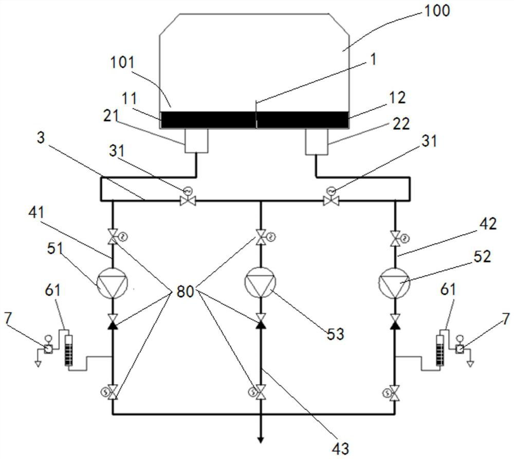
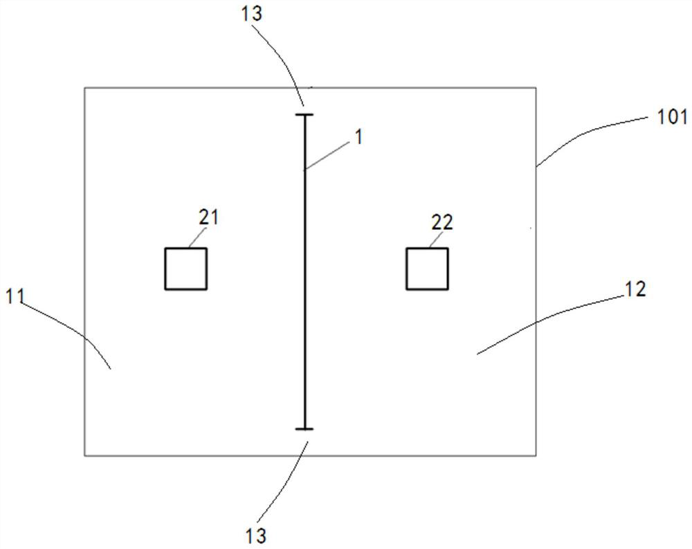
[0038]SeeFigure 1 ~ 2A condensate pump arrangement method provided by the present invention includes: a partition plate 1 is disposed vertically in the inner surface of the bottom plate of the condenser 100, the separator 1 to condense the condensed water cavity in the hot well 101 The first condensate cavity 11 and the second condensate cavity 12, the first condensate cavity 11, and the second condensate cavity 12 are communicated between the first condensate cavity 12; in the hot well 101 corresponding to the first condensate cavity 11. The outer surface of the bottom plate is provided with a first collector 21, and the inlet end of the first collector 21 communicates with the inner side of the first condensate chamber 11, outside the bottom plate corresponding to the hot well 101 of the second condensate cavity 12. A second collector 22 is provided with an inner side of the second collector 22 in the inner side of the second condensate chamber 12; the water end of the first colle...

Embodiment 2

[0060]The sides of the partition plate 1 have a gap 13 between the adjacent side walls of the hot well 101, and the first condensed water chamber 11 and the second condensate cavity 12 are passed through the The gap 13 forms a communication.

[0061]The gap 13 is provided on both sides to ensure stability of the first condensate cavity 11 and the second condensate cavity 12, ensuring that the first condensate cavity 11 and the second condensate cavity 12 are consistent.

[0062]The rest is the first embodiment.


PUM


Abstract

The invention relates to a condensate pump arrangement method. The method comprises the steps that a partition plate is vertically arranged on the inner surface of a bottom plate of a hot well of a condenser; a first water collector and a second water collector are arranged; the water outlet end of the first water collector and the water outlet end of the second water collector are connected through a condensate header pipe; two stop valves are arranged on the condensate header pipe; a first condensate branch pipe, a second condensate branch pipe and a standby condensate branch pipe are connected; a first condensate pump is arranged on the first condensate branch pipe, a second condensate pump is arranged on the second condensate branch pipe, and a standby condensate pump is arranged on the standby condensate branch pipe; and a first sampling and testing device is arranged on the first condensate branch pipe, and a second sampling and testing device is arranged on the second condensate branch pipe. According to the arrangement method, condensate in a first condensate cavity and condensate in a second condensate cavity in the hot well of the condenser can be pumped out, and the problem that only one water collector is arranged in the hot well, and consequently the condensate on the two sides cannot be pumped out separately is solved.

Description

Technical field[0001]The present invention belongs to the technical field of power generation equipment, and more particularly to a condensate water pump arrangement for a wet-cooling fire generator, which is also suitable for gas turbine, nuclear power, waste heat generating electricity such as a condensed steam turbine.Background technique[0002]The domestic wet cold fire power unit is arranged inside the condenser arranged for 10,000 heat transfer tubes, and the circulating water cooled into the condenser, and the steam is condensed into water in the outer surface of the heat exchange pipe, flowing into the bottom of the condenser.[0003]Due to wear and impact, the power plant is facing the problem of leakage of condenser changing heat pipes. Since there is a huge difference in condensed water and cooling of the condenser inside the condenser, once the heat exchanger occurs, the unqualified circulating water will enter the negative pressure side of the condenser, resulting in conde...

Claims


Application Information

Patent Timeline
IPC IPC(8): F01K9/02
CPCF01K9/02F01K9/023Y02E10/10
Inventor 刘平升张忠华杨志佳王峰林旭宏孙涛
Owner HUANENG POWER INTERNATIONAL
Why Eureka
Try Eureka