Hot water recirculation system for waste heat recovery of flue gas

A recirculation system and flue gas waste heat technology, applied in the directions of preheating, heat exchanger, supplementary water supply, etc., can solve the problem that the waste heat of flue gas cannot be fully recovered, reduce the recovery efficiency of waste heat from flue gas, increase the initial investment of equipment and the difficulty of project implementation and other problems, to achieve the effect of stable flow, reducing coal consumption for power supply, and reducing power consumption

Pending Publication Date: 2020-03-06
石家庄良村热电有限公司 +1
View PDF0 Cites 3 Cited by
  • Summary
  • Abstract
  • Description
  • Claims
  • Application Information

AI Technical Summary

Problems solved by technology

However, for the extraction condensing steam turbine generator set, if it is operating under the condition of large extraction steam, since the condensate flow rate at the outlet of the 7th stage low pressure heater 2 is much smaller than the pure condensing condition, if the condensing Water is used as the working medium, which will cause exhaust waste heat to be unable to be fully recovered
If a two-stage cycle is used (as attached figure 2 ), the flow rate of the working medium entering the flue gas waste heat recovery heat exchanger 6 remains unchanged, and the recovered heat is exchanged through the water-water heat exchanger 9, then the driving water pump 3 and the water-water heat exchanger 9 need to be added in the system , while reducing the efficiency of flue gas waste heat recovery, increasing the initial investment of equipment and the difficulty of project implementation

Method used


Image

  • Hot water recirculation system for waste heat recovery of flue gas
  • Hot water recirculation system for waste heat recovery of flue gas
  • Hot water recirculation system for waste heat recovery of flue gas

Examples


Embodiment Construction

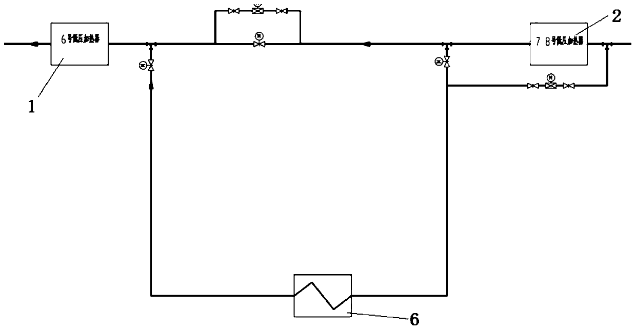
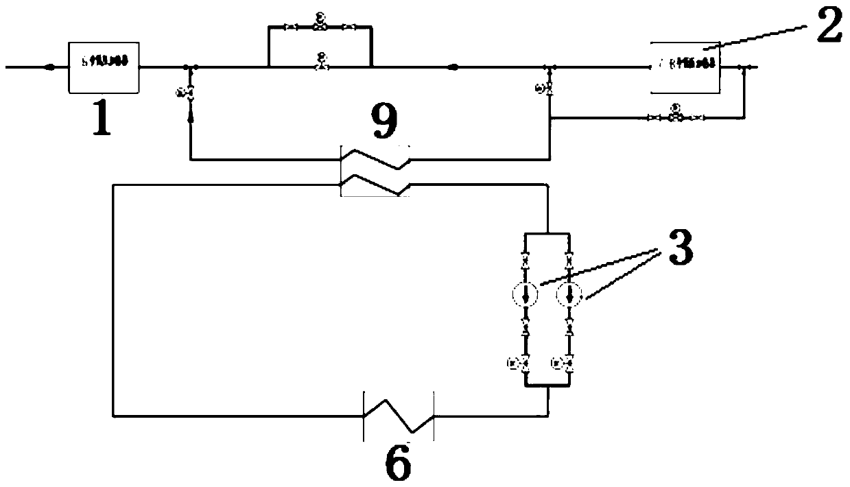
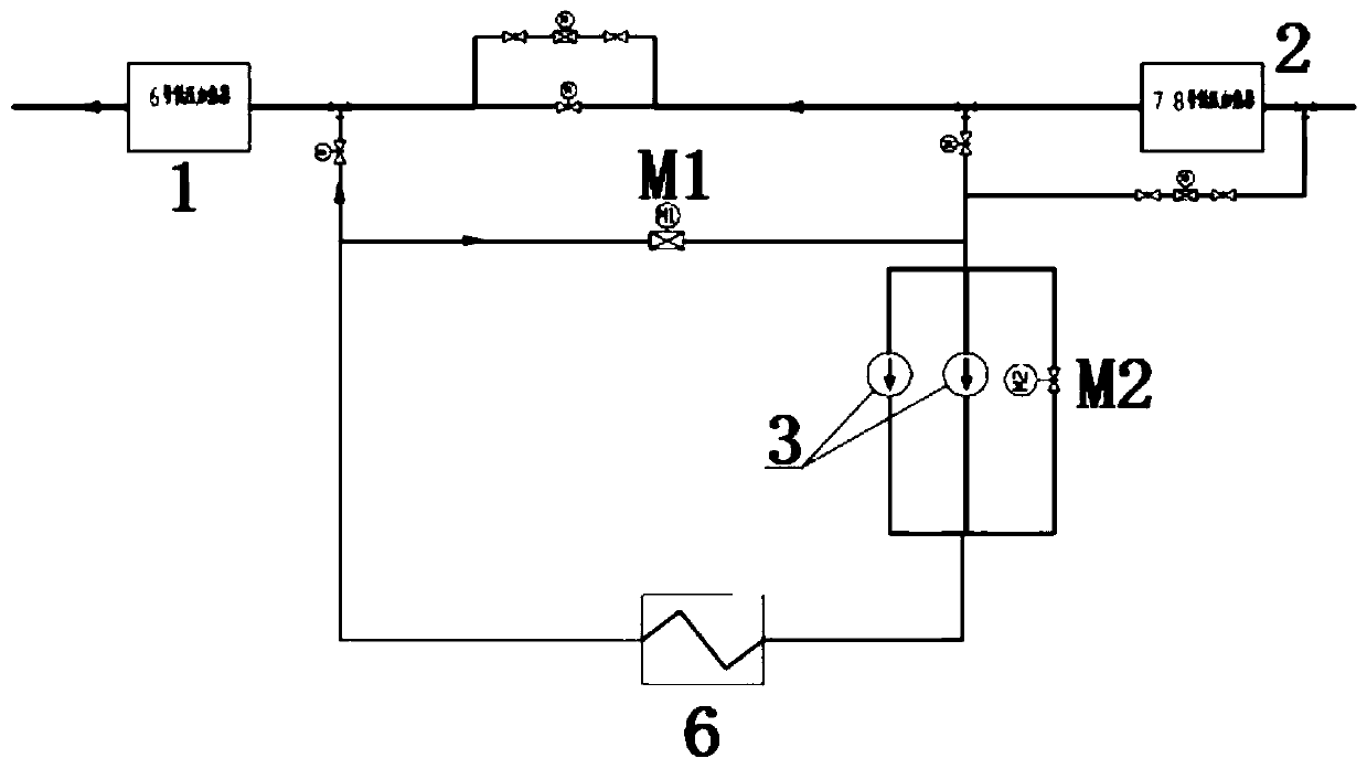
[0020] In order to make the present invention more comprehensible, the preferred embodiments are described in detail as follows in conjunction with the accompanying drawings;

[0021] like Figure 1-6 As shown, the present invention provides a hot water recirculation system for flue gas waste heat recovery, and the flue gas waste heat is connected in parallel between the 7th or 8th low-pressure heater 2 of the steam turbine and the 6th low-pressure heater 1 The recovery heat exchanger 6; and the flue gas waste heat recovery heat exchanger 6 are connected in parallel to the regulating valve M1; a gate valve M2 and two booster pumps 3 are arranged between the regulating valve M1 and the flue gas waste heat recovery heat exchanger 6; The one gate valve M2 and the two booster water pumps 3 are connected in parallel and connected in series with the flue gas waste heat recovery heat exchanger 6 . A manual valve 4 is arranged in series at the inlet or outlet of the regulating valve ...


PUM


Abstract

The invention provides a hot water recirculation system for waste heat recovery of flue gas, and belongs to the technical field of thermal power energy conservation. The hot water recirculation systemis characterized in that heaters and a flue gas waste heat recovery heat exchanger are connected in parallel to access an adjusting valve; a gate valve and a booster water pump are additionally arranged, and the adjusting valve ensures that condensed water flow entering the flue gas waste heat recovery heat exchanger when an extracting and condensing steam turbine is operated under the steam extraction working condition is stable; a bypass valve is arranged at the booster water pump, the booster water pump does not operate when the steam turbine is in a pure condensing condition, the bypass valve is opened, the system relies on the unit condensation water pump margin to form an open cycle, the power consumption of the system can be reduced, and the power supply coal consumption is reduced; and after the flue gas waste heat recovery heat exchanger is added, an air heater is additionally arranged, so that the flue gas waste heat recovery system realizes multiple modes of operation, theload regulation range is large, and the unit adaptability is good. According to the hot water recirculation system, the waste heat recovery rate of the smoke exhaust is improved, the initial investment of the equipment is reduced, the adjustment is flexible, the energy-saving effect is remarkable, and the engineering implementation difficulty is reduced.

Description

technical field [0001] The invention relates to a hot water recycling system for flue gas waste heat recovery, and belongs to the technical field of thermal power generation and energy saving. Background technique [0002] Coal price is the main factor affecting the economic benefits of coal-fired power plants. The flue gas waste heat recovery system can save the coal consumption of power generation because it can recover the waste heat from the boiler exhaust. At present, it has become a standard equipment in new coal-fired power generation units in my country, and the old power generation units are gradually undergoing energy-saving retrofitting and installing this system. The flue gas waste heat recovery system usually uses the exhaust gas of the boiler to heat the condensate water of the unit (if attached figure 1 ), usually use condensed water from the 7th or 8th low-pressure heater 2 of the steam turbine as the heat transfer medium, and connect between the 7th or 8th ...

Claims


Application Information

Patent Timeline
Patent Type & Authority Applications(China)
IPC IPC(8): F22D11/06F28D21/00F28F27/00
CPCF22D11/06F28D21/0014F28F27/00
Inventor 刘江宁华志刚刘瑞林李明宇万鹏谭学靖韩龙王建雷承勇
Owner 石家庄良村热电有限公司
Why Eureka
Try Eureka