Secondary ejection type injection mold and injection molding method thereof

An injection mold, secondary ejection technology, applied in the field of injection molding, to achieve the effect of avoiding contact adhesion

Pending Publication Date: 2021-05-04
广州市旭胜模具有限公司
View PDF1 Cites 0 Cited by
  • Summary
  • Abstract
  • Description
  • Claims
  • Application Information

AI Technical Summary

Problems solved by technology

There are problems when the existing injection mold is used to inject the anti-scratch strip of the car door: soft plastic injection molded parts usually have a certain adhesion to the smooth cavity, and generally need to be demoulded manually or mechanically

Method used


Image

  • Secondary ejection type injection mold and injection molding method thereof

Examples


Embodiment Construction

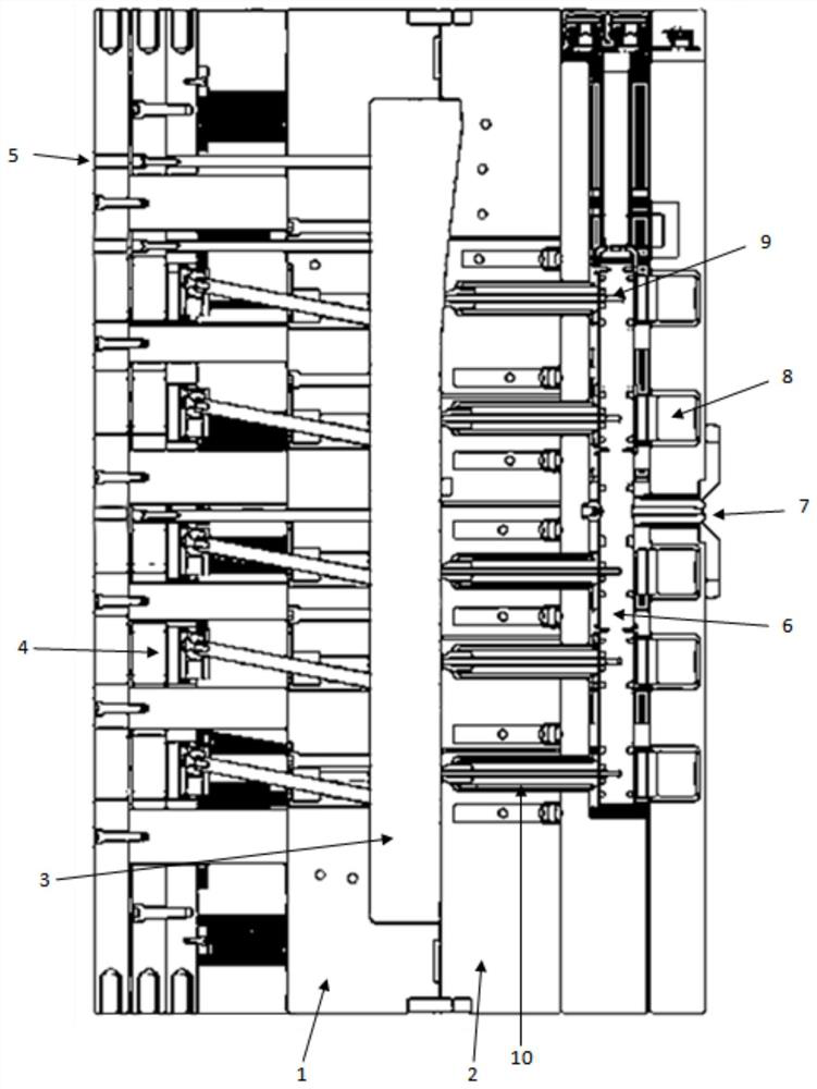
[0020] The specific embodiment of the present invention will be further described below in conjunction with accompanying drawing:

[0021] Such as figure 1 As shown, a secondary ejection type injection mold includes a left mold and a right mold. A cavity is formed at the junction of the left mold and the right mold. The left mold is equipped with five ejection mechanisms and three blowout mechanisms corresponding to the cavity. Air mechanism, there is a sprue at the right end of the right mold, a main sprue and five secondary sprues are arranged in the right mold, the main sprue is connected with the gate and five secondary sprues, and the outer periphery of the secondary sprue is wrapped with a heating jacket , five electric heating plates are arranged on the side wall of the main runner.

[0022] The thimble of the ejection mechanism is arranged obliquely downward, which is convenient for pushing out the injection molded part obliquely downward.

[0023] The blowing mechan...


PUM


Abstract

The invention relates to the technical field of injection molding, in particular to a secondary ejection type injection mold and an injection molding method thereof. The mold comprises a left mold and a right mold, wherein a cavity is formed at the junction of the left mold and the right mold, the left mold is provided with five ejection mechanisms and three blowing mechanisms corresponding to the cavity, the right end of the right mold is provided with a pouring gate, a main pouring gate and five secondary pouring gates are arranged in the right mold, the main pouring gate communicates with the pouring gate and the five secondary pouring gates, and the peripheries of the secondary pouring gates are wrapped with heating sleeves; and five electric heating trays are arranged on the side wall of the main pouring gate. First-time ejection is completed through the blowing mechanisms, so that a soft injection molding part is separated from the left mold in a soft and effective mode; then second-time ejection is completed through the ejection mechanisms, so that the injection molding part is forced to be separated from the mold range rapidly through rigid and rapid actions, and thus, the injection molding part is prevented from being in contact and adhesion with the mold again.

Description

technical field [0001] The invention relates to the technical field of injection molding, in particular to a secondary ejection injection mold and an injection molding method thereof. Background technique [0002] The door anti-scratch strip is usually made of flexible plastic injection molding (such as silica gel), and the soft and elastic plastic injection molded parts form a protection for the edge of the door, so as to prevent the car on the adjacent parking space from being damaged when the door is opened. There are problems when the existing injection molds are used to inject anti-scratch strips for car doors: soft plastic injection molded parts usually have a certain adhesion to a smooth cavity, and generally need to be demoulded manually or mechanically. Contents of the invention [0003] Aiming at the deficiencies of the prior art, the invention provides a secondary ejection injection mold that is easy to demould. [0004] Technical scheme of the present inventio...

Claims


Application Information

Patent Timeline
IPC IPC(8): B29C45/27B29C45/73B29C45/40B29C45/43
CPCB29C45/2725B29C45/2738B29C45/2737B29C45/4005B29C45/43B29C2045/2743
Inventor 陈国樑李艺杰刘素优
Owner 广州市旭胜模具有限公司
Why Eureka
Try Eureka