Laser device

a laser device and laser technology, applied in semiconductor lasers, electrographic processes, instruments, etc., can solve the problems of irradiation of ultraviolet light on uv-curing adhesives, trouble of coating adhesives, and unsatisfactory design of laser devices, so as to improve adhesion strength, simplify the operation of coating adhesives, and increase the adhesion strength

Inactive Publication Date: 2008-11-25
E PIN OPTICAL IND
View PDF7 Cites 2 Cited by
  • Summary
  • Abstract
  • Description
  • Claims
  • Application Information

AI Technical Summary

Benefits of technology

[0004]Therefore it is a primary object of the present invention to provide a laser device that includes a laser diode disposed on a flange. And an inner tube part of a holder is disposed with a collimator lens on one end while the other end of the inner tube part faces the laser diode so that the laser beam passes through the inner tube part of the holder and the collimator lens, then projects out. At least one lug extends radically from outer surface of the holder and a plurality of axial guide slots is disposed on the lug. A plurality of guide pins corresponding to the guide slots is arranged on the flange. By assembling as well as adjustment between the guide pins and the guide slots, and adhesion of the UV-curing type adhesive, the laser diode and the collimator lens are integrated into one part so as to increase the adhesion strength and prevent the collimator lens from contacting the adhesive while coating the UV-curing type adhesive by conventional techniques.
[0005]It is another object of the present invention to provide a laser device that assembles the flange with the holder by combination of the axial guide pins on the flange with the corresponding axial guide slots on the holder. The guide pin can be two-guide-pin type, three-guide-pin type, or four-guide-pin type and is applied according to different jigs for calibration of X axis, Y axis, and Z axis and the adhesion strength is also enhanced.
[0006]It is a further object of the present invention to provide a laser device that a plurality of axial guide slots on the lug can be close-ended or open-ended so as to simplify operations of coating adhesives and UV light irradiation, increase operation efficiency and enhance adhesion strength.

Problems solved by technology

However, the design of the laser device is not ideal.
Refer to Japanese patent application No. 08-112940, a holder disposed with a collimator lens is arranged on front end of the holder with a laser diode while the UV-curing type adhesive is painted between the inner tube and outer tube of two holders so that there is a trouble of irradiating the UV light on the UV-curing type adhesive.
Although the UV light can irradiate the UV-curing type adhesive, the UV-curing type adhesive may contact the holder and cause trouble of coating the adhesive.
Because the collimator lens is attached on the holder just by the circular surface, the adhesion strength is not enough and easy to get damage while being bumped.
Although the UV-curing type adhesive can be irradiated by the UV light and the adhesion strength is assured, the UV-curing type adhesive may still contact with the collimator lens and cause trouble.

Method used


Image

  • Laser device
  • Laser device
  • Laser device

Examples


Embodiment Construction

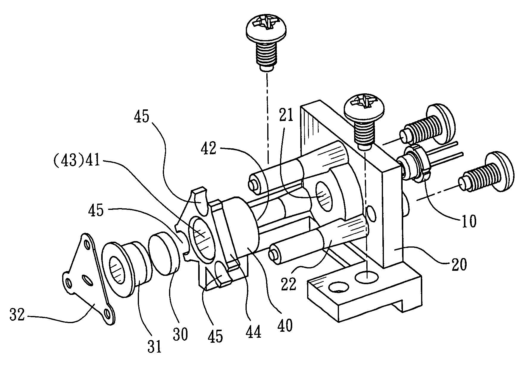
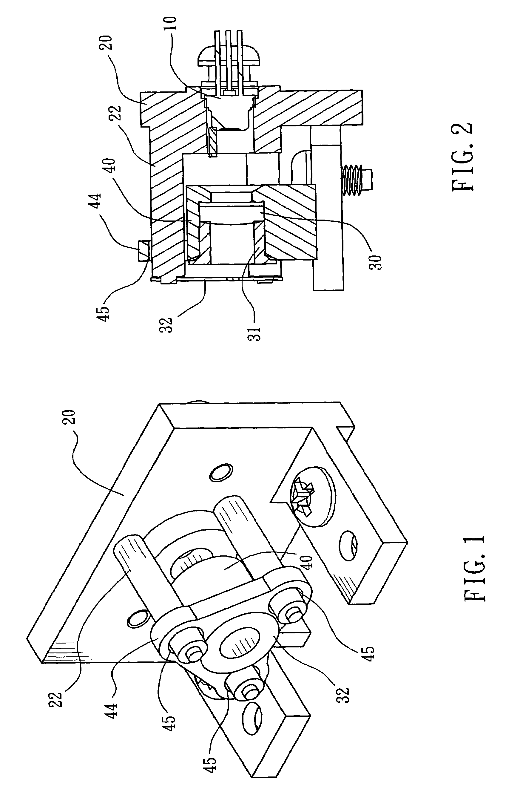
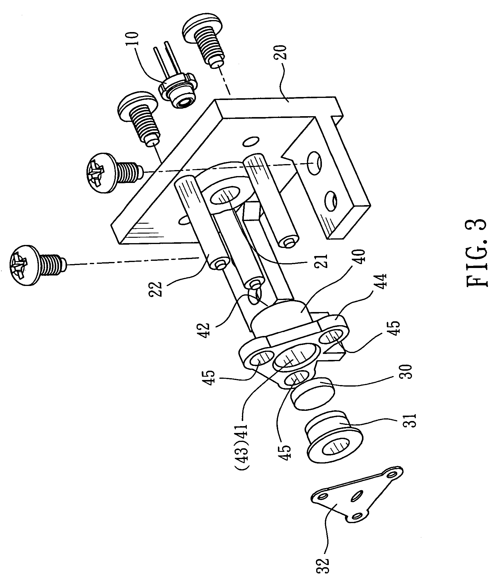
[0023]Refer from FIG. 1 to FIG. 3, a laser device according to the present invention applied to a light source of laser scanning units (LSU) consists of a laser diode 10, a flange 20, a collimator lens 30, and a holder 40 for collimator lens. The laser diode 10 is fixed on a circuit substrate and is mounted projecting inside an accommodation hole 21 on the flange 20 for emitting laser beam forwardly. The flange 20 is fastened on a housing of the laser scanning unit. The holder 40 is a tube with an inner tube part 41 while one end (rear end) 42 of the inner tube part 41 faces the laser diode 10 and the collimator lens 30 is mounted in the other end (front end) 43 of the inner tube part 41. Thus the laser beam passes through the inner tube part 41 of the holder 40 and the collimator lens 30, then projects out. In assembling, the front end of the collimator lens 30 is pressed by a ring 31 for preventing the collimator lens 30 from separating from the holder 40.

[0024]Moreover, an apertu...


PUM


Abstract

A laser device applied to a light source of laser scanning units (LSU) including a laser diode disposed on an accommodation hole of a flange. A collimator lens is arranged on one end of an inner tube part of a holder while the other end of the inner tube part faces the laser diode. The laser beam passes through the inner tube part of the holder and the collimator lens, then projects out. A lug extends radially from outer surface of the holder and a plurality of axial guide slots are disposed on the lug. A plurality of guide pins corresponding to the guide slots are arranged on the flange. An adhesive is located between the guide pins and the guide slots and spaced apart from the collimator lens.

Description

BACKGROUND OF THE INVENTION[0001]The present invention relates to a laser device applied to a light source of laser scanning units (LSU), especially to a laser device that connects a laser with a collimator by guide pins for calibration and adhesion.[0002]A conventional Laser Beam Printer includes a Laser Scanning Unit that uses a laser diode as a light source. A light beam emitted from the laser diode passes a collimator lens and becomes a parallel light bean, then through a cylinder lens for converging the light beam that passes along Y axis of a sub-major scanning direction, and directly transmits the light beams along X-axis of a main scanning direction so as to form a line image. A high-speed polygon mirror that deflects the at least one light beam is disposed near or in focus of above image for controlling projecting direction of the laser beam so as to make the laser beam move parallel to X-axis of the main scanning direction in a constant angular velocity, and then being def...

Claims


Application Information

Patent Timeline
Patent Type & Authority Patents(United States)
IPC IPC(8): H01S3/08
CPCG02B7/025H01S5/02288G02B19/0052G02B19/0014G03G15/04072G03G15/0409H01S5/02253
Inventor SHYU, SAN-WOEICHEN, GUO-ZENWEN, MING-HUACHU, I-LIN
Owner E PIN OPTICAL IND
Why Eureka
Try Eureka