
Method for determining comb spectrum interference signal frequency points in multiple limited bandwidth ranges

An interference signal, limited bandwidth technology, applied in transmission monitoring, electrical components, transmission systems, etc., can solve the problems of affecting accuracy, lack, conflict of working bandwidth range, etc., to achieve the effect of avoiding conflict

Active Publication Date: 2021-05-04
NO 20 RES INST OF CHINA ELECTRONICS TECH GRP
View PDF4 Cites 0 Cited by
  • Summary
  • Abstract
  • Description
  • Claims
  • Application Information

AI Technical Summary

Problems solved by technology

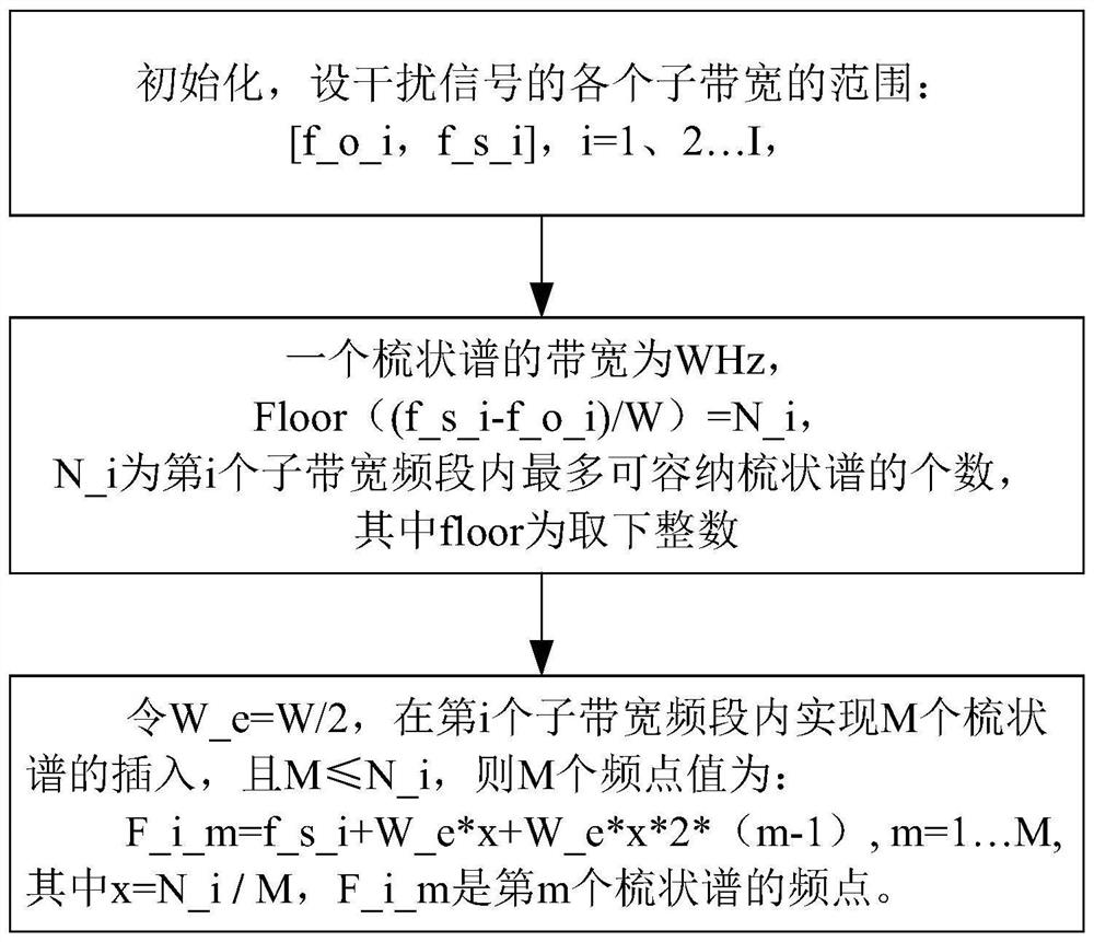
[0003] The current methods for determining the frequency points of comb spectrum interference signals in a limited bandwidth range are mainly based on the direct average division of the working frequency band, and the insertion of comb spectrum interference signals at the division points. Although these solutions are simple and direct, they lack the same The relationship between the bandwidth of the interference signal, especially when the bandwidth of the comb spectrum interference signal is large, inserting the comb spectrum interference signal at the split point will conflict with the working bandwidth range. To determine the accuracy of frequency points of comb spectrum interference signals, it is necessary to propose a new method for determining the frequency points of comb spectrum interference signals within a limited bandwidth range.

Method used


Image

  • Method for determining comb spectrum interference signal frequency points in multiple limited bandwidth ranges

Examples


Embodiment Construction

[0013] The present invention will be further described below in conjunction with the accompanying drawings and embodiments.

[0014] The invention provides a method for determining frequency points of comb spectrum interference signals within a plurality of limited bandwidth ranges. The core idea is to obtain the insertion frequency points of each comb spectrum based on the ratio of the maximum number of combs that can be inserted to the actual number of combs that need to be inserted, and to generate combs with different frequency intervals based on different finite bands. Calculate the maximum number of combs that can be inserted in a certain limited bandwidth, and obtain the insertion frequency points of each comb based on the ratio of the maximum number of combs that can be inserted to the actual number of combs that need to be inserted, so that different frequency bands Different working frequencies produce precise interference.

[0015] A method for determining frequenc...


PUM


Abstract

The invention provides a method for determining frequency points of comb spectrum interference signals in a plurality of limited bandwidth ranges, and the method comprises the following steps: generating comb spectrums with different frequency intervals based on different limited bands in a targeted manner, and calculating the maximum number of the comb spectrums which can be inserted into a certain limited bandwidth; obtaining the insertion frequency point of each comb spectrum based on the ratio of the maximum number of the comb spectrums which can be inserted to the number of the comb spectrums which need to be inserted actually, so accurate interference is generated on different working frequency points of different frequency bands. According to the method, the maximum number of the comb spectrums which can be inserted into a certain limited bandwidth is calculated, and the insertion frequency point of each comb spectrum is obtained based on the ratio of the maximum number of the comb spectrums which can be inserted into the limited bandwidth to the number of the comb spectrums which actually need to be inserted into the limited bandwidth, so accurate interference is generated on different working frequency points of different frequency bands, and conflicts between a plurality of limited bandwidth ranges and the total comb spectrum bandwidth are avoided.

Description

technical field [0001] The invention relates to related technical fields such as mobile communication and digital signal processing, in particular to a method for estimating interference frequency points. Background technique [0002] In order to generate comb spectrum interference signals for digital receivers operating in multiple limited bandwidth ranges, so as to achieve targeted interference on one or more frequency points in signals of different operating bandwidth bands, a multiple limited bandwidth range A method for determining frequency points of comb spectrum jamming signals is proposed. This technology is based on the targeted generation of comb spectra with different frequency intervals based on different finite bands. By calculating the maximum number of comb spectra that can be inserted in a certain limited bandwidth, based on the maximum number of comb spectra that can be inserted and the actual number of comb spectra that need to be inserted The ratio of th...

Claims


Application Information

Patent Timeline
Patent Type & Authority Applications(China)
IPC IPC(8): H04B17/30H04B17/345
CPCH04B17/345H04B17/30
Inventor 黄子甲文明王苏乐
Owner NO 20 RES INST OF CHINA ELECTRONICS TECH GRP
Learn More