
Polarizer

A polarizer and polarizing mirror technology, applied in the microwave field, can solve problems such as complex adjustment structure, high installation accuracy, and difficult maintenance, so as to achieve efficient coupling and ensure microwave sealing

Active Publication Date: 2021-05-04
ENN SCI & TECH DEV
View PDF7 Cites 0 Cited by
  • Summary
  • Abstract
  • Description
  • Claims
  • Application Information

AI Technical Summary

Problems solved by technology

[0003] The polarizing mirror in the polarizer in the prior art has two control modes: manual control and mechanical automation control, but the response speed of the manual control mode is slow and the precision is low, so that the efficient coupling of the wave and the plasma cannot be guaranteed; the automatic control Although the method has fast response and high precision, its adjustment structure is more complicated and the installation accuracy is higher. Once a problem occurs, it needs to be re-adjusted and the maintenance cycle is longer. The complex structure makes maintenance more difficult and reduces work efficiency.

Method used


Image

  • Polarizer
  • Polarizer
  • Polarizer

Examples


Embodiment Construction

[0023] In order to more clearly understand the above objects, features and advantages of the present invention, the present invention will be further described in detail below in conjunction with the accompanying drawings and embodiments. It should be understood that the described embodiments are some, not all, embodiments of the present invention. The specific embodiments described here are only used to explain the present invention, but not to limit the present invention. All other embodiments obtained by those skilled in the art based on the described embodiments of the present invention belong to the protection scope of the present invention.

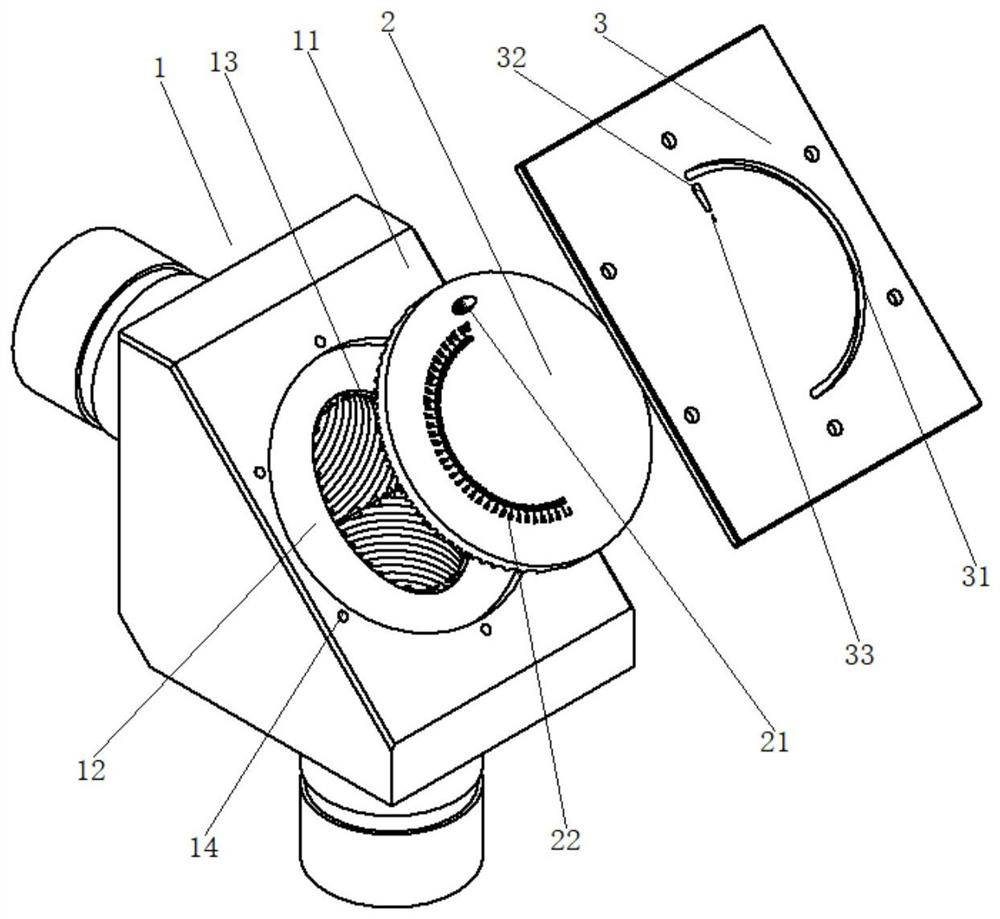
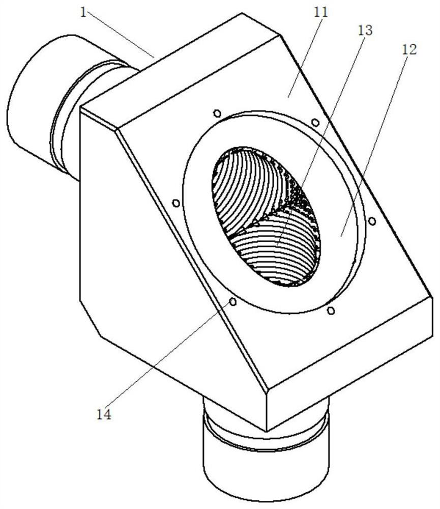
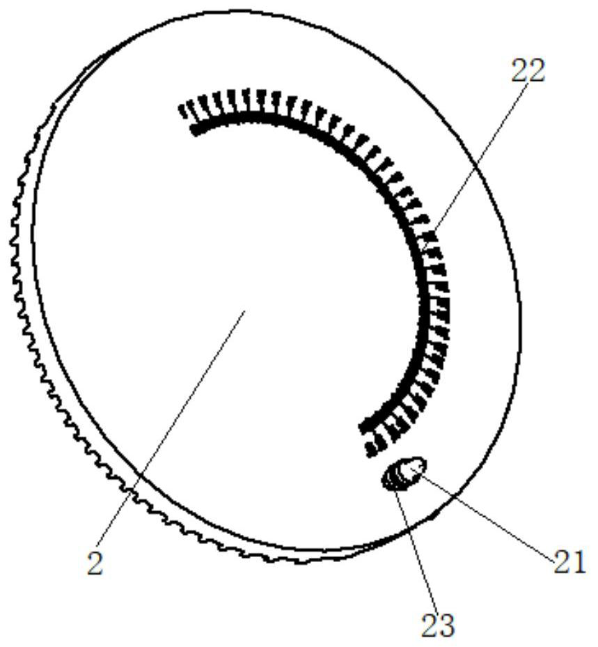
[0024] Such as figure 1 As shown, a polarizer provided by the present invention includes a reversing elbow 1 and a polarizing mirror 2. Two microwave channels connected vertically to each other are arranged in the reversing elbow 1 for microwave transmission. The elbow 1 includes a mounting surface 11 at an angle of 45° to the axi...


PUM


Abstract

The invention relates to the technical field of microwaves, and provides a polarizer. The polarizer comprises a reversing elbow and a polarization mirror, wherein two microwave channels which communicate with each other are arranged in the reversing elbow; the reversing elbow comprises a mounting surface used for arranging the polarization mirror; a groove is formed in the mounting surface; a through hole which communicates with a connecting inflection point of the two microwave channels is formed in the middle of the groove; the polarization mirror is partially or completely arranged in the groove; the front surface of the polarization mirror covers the through hole, and the back surface of the polarization mirror is provided with a deflector rod; a cover plate is arranged at an opening of the groove and is connected with the mounting surface; an adjusting hole for the deflector rod to extend out is formed in the cover plate; and the deflector rod rotates or slides relative to the adjusting hole so as to allow the polarization mirror to rotate in the groove; According to the invention, a microwave polarization angle is accurately adjusted, and efficient coupling of microwaves and plasmas is achieved.

Description

technical field [0001] The invention belongs to the field of microwave technology, in particular to a polarizer. Background technique [0002] In electron cyclotron resonance heating systems, microwaves reaching the resonant layer require specific microwave polarization forms to carry out ordinary mode or extraordinary mode heating. The ratio of ordinary mode and extraordinary mode depends on the microwave polarization form and incident angle. When changing the plasma operating parameters or microwave incident angle, the microwave polarization form must be changed to achieve efficient coupling between the wave and the plasma. In the process of wave transmission, it is necessary to use a polarizer to change the polarization direction of the microwave so that it hits the plasma in the specified direction. The polarization direction is of great significance for the coupling of microwave and plasma. Microwaves with different polarization directions have different propagation tr...

Claims


Application Information

Patent Timeline
Patent Type & Authority Applications(China)
IPC IPC(8): H05B6/64
CPCH05B6/6402
Inventor 马放宋绍栋
Owner ENN SCI & TECH DEV
Learn More