Eureka AIR delivers breakthrough ideas for toughest innovation challenges, trusted by R&D personnel around the world.

Device for determining radar target lis, sensor system and method

A radar sensor, radar target technology, applied in radio wave measurement systems, instruments, utilization of re-radiation, etc., can solve problems such as increased computational complexity, inaccuracy, target repetition, etc.

Pending Publication Date: 2021-05-07
ZF FIEDRICHSHAFEN AG
View PDF0 Cites 0 Cited by
  • Summary
  • Abstract
  • Description
  • Claims
  • Application Information

AI Technical Summary

Problems solved by technology

[0007] The disadvantage of additional observation of the neighborhood when evaluating the individual high points is that adjacent objects in the range-velocity range often influence each other
This may result in inaccuracies or false detections
A solution using dual-objective modeling leads to a significant increase in computational complexity and may also cause duplication of objectives

Method used


Image

  • Device for determining radar target lis, sensor system and method
  • Device for determining radar target lis, sensor system and method
  • Device for determining radar target lis, sensor system and method

Examples


Embodiment Construction

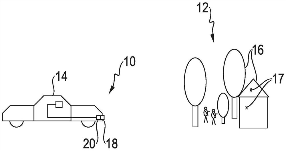
[0036] exist figure 1 A sensor system 10 according to the invention for detecting objects in an environment 12 of a vehicle 14 is schematically shown in FIG. In the illustrated example, sensor system 10 is an automotive radar system integrated into vehicle 14 . Objects 16 in the surroundings 12 of the vehicle can be detected as individual objects 17 . It is likewise possible for individual objects 16 to form a plurality of targets 17 in the radar target list.

[0037] Sensor system 10 includes radar sensor 18 and device 20 . The radar sensor 18 is preferably designed as a frequency-modulated multi-pulse radar sensor (FMCW radar sensor) and generates sensor data which reflect the surroundings 12 of the vehicle 14 . A radar target list is determined in device 20 , which can be used to generate an image of the surroundings in order, for example, to enable autonomous operation of vehicle 14 or to support the driver.

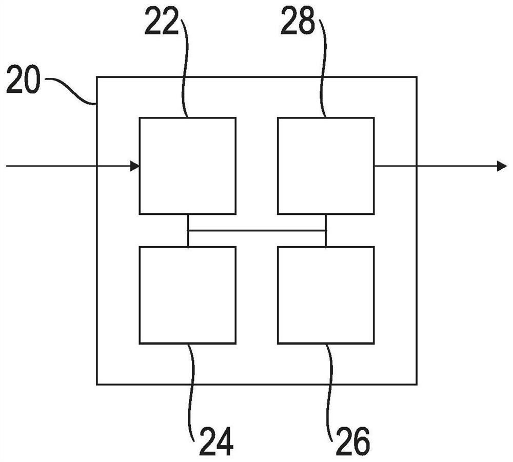
[0038] exist figure 2 A device 20 according to the invent...


PUM


Abstract

The present invention relates to a device for determining a radar target list, comprising: an input interface for receiving preprocessed sensor data from a radar sensor with information on detected strengths at high points in a distance and / or velocity dimension and in predefined neighborhood ranges of the high points in the distance and / or velocity dimension; an analysis unit for determining mutually adjacent high points with overlapping neighborhood ranges based on the preprocessed sensor data; an adjustment unit for adjusting the neighborhood ranges of the mutually adjacent high points; and an evaluation unit for determining a radar target list with information on targets in a field of view of the radar sensor based on the high points and the neighborhood ranges thereof. The present invention also relates to a method for determining a radar target list and a sensor system for detecting targets in an environment of a vehicle.

Description

technical field [0001] The invention relates to a device for determining a radar target list. The invention also relates to a sensor system for detecting objects in the surroundings of a vehicle and a method for determining a radar object list. Background technique [0002] Today's vehicles (cars, trucks, trucks, motorcycles, etc.) have a multitude of sensors that provide information to the driver and control individual functions of the vehicle semi-automatically or fully automatically. The surrounding environment of the vehicle and other traffic participants are recorded by sensors. A model of the vehicle's surroundings can be generated based on the recorded data and a response to changes in this vehicle's surroundings can be made. [0003] The key sensor principle here is radar technology. Radar sensors commonly used today in the vehicle sector operate as multi-pulse radar sensors (also referred to as chirp radar sensors), in which a plurality of frequency-modulated pul...

Claims


Application Information

Patent Timeline
Patent Type & Authority Applications(China)
IPC IPC(8): G01S7/41G01S7/292G01S13/931
CPCG01S7/415G01S7/2923G01S13/931G01S7/352G01S7/412G01S13/584G01S13/42
Inventor B·西克S·泽克纳F·恩格斯
Owner ZF FIEDRICHSHAFEN AG
Why Eureka
Eureka Blog
Learn More