
Self-cleaning ventilation equipment

A ventilation equipment and self-cleaning technology, applied in ventilation systems, mechanical equipment, lighting and heating equipment, etc., can solve problems affecting normal use, manual cleaning, difficulty in reducing air dust content, etc.

Inactive Publication Date: 2021-05-11
王小丽
View PDF6 Cites 2 Cited by
  • Summary
  • Abstract
  • Description
  • Claims
  • Application Information

AI Technical Summary

Problems solved by technology

High-rise buildings need to be ventilated during the use of high-rise buildings to ensure faster internal air circulation. Existing ventilation devices mostly use blowers for air delivery. The structure is relatively simple, and it is difficult to effectively filter the air, affecting the device. normal work, and the existing ventilation device is difficult to reduce the dust content in the air, the ventilation effect is not good
[0003] The Chinese utility model patent announcement number is CN211575394U, which proposes a ventilation device for buildings. It is provided with a filter layer and a rotating device to filter the air, so that the dust and dirt content of the conveyed air is lower, and the protective net can effectively prevent the outside world from Large-scale debris enters the device and causes damage to the device. However, during use, a large amount of dust in the external air will accumulate on the filter layer, and the higher the dust content in the external air, the faster the dust will accumulate on the filter layer. A large amount of dust will accumulate on the filter layer in a short time, and the dust will block the filter layer, resulting in lower and lower ventilation efficiency and affecting normal use. Therefore, the filter screen and filter layer need to be cleaned manually frequently, which is time-consuming and laborious

Method used


Image

  • Self-cleaning ventilation equipment
  • Self-cleaning ventilation equipment
  • Self-cleaning ventilation equipment

Examples


Embodiment Construction

[0022] In order to make the object, technical solution and advantages of the present invention clearer, the present invention will be further described in detail below in combination with specific embodiments and with reference to the accompanying drawings. It should be understood that these descriptions are exemplary only, and are not intended to limit the scope of the present invention. Also, in the following description, descriptions of well-known structures and techniques are omitted to avoid unnecessarily obscuring the concept of the present invention.

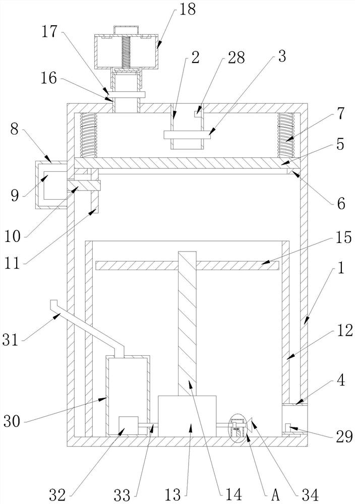
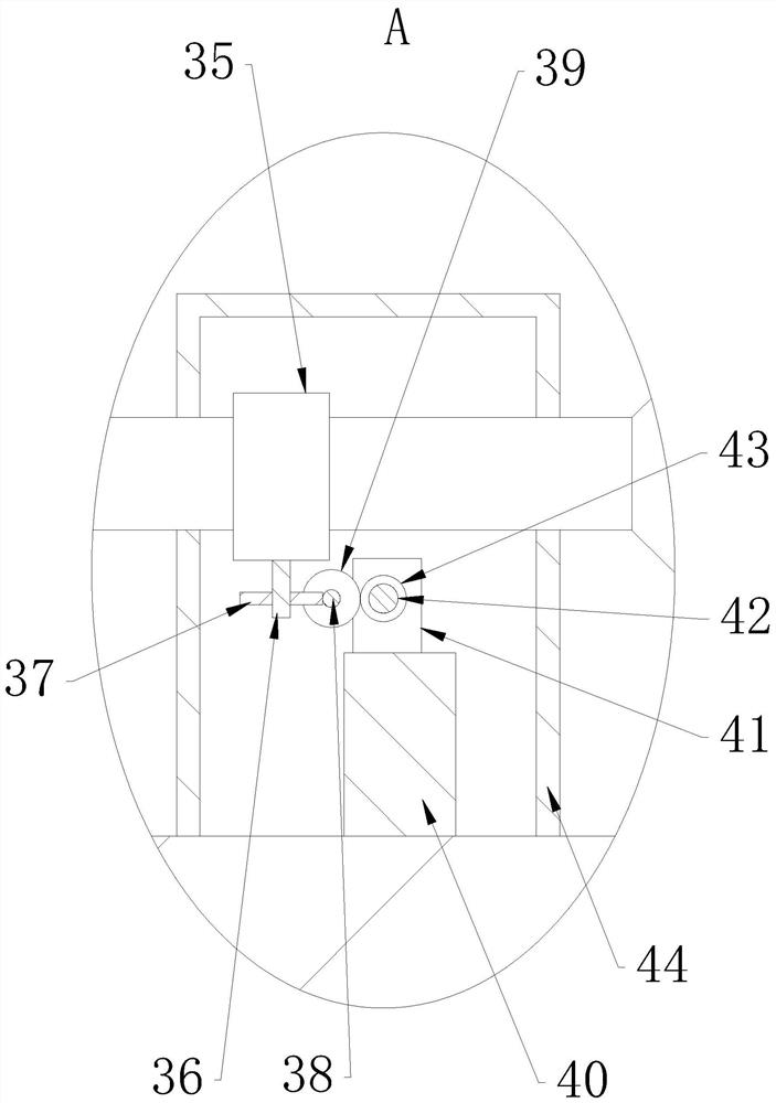
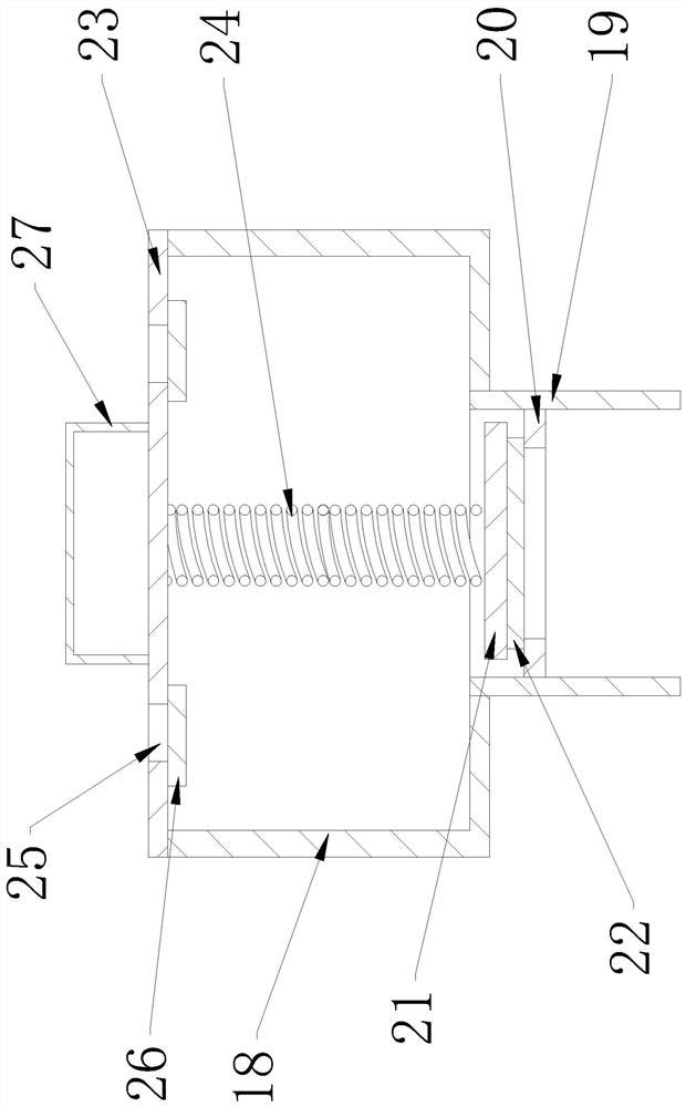
[0023] Such as Figure 1-3 As shown, a self-cleaning ventilator proposed by the present invention includes a box body 1, a first stop ring 6, a first spring 7, a cylinder body 12, a second power device 13, a second rotating shaft 14, an outlet Dust pipe 16 and dust collection assembly; dust collection assembly includes dust collection box 18, dust inlet pipe 19, pressure plate 21, second spring 24, second filter screen 2...


PUM


Abstract

The invention relates to self-cleaning ventilation equipment which comprises a box body, a first limiting ring, a first spring, a barrel body, a second power device, a second rotating shaft, a dust outlet pipe and a dust collecting assembly. An air inlet pipe is arranged at the top of the box body and provided with a first electromagnetic valve; an air outlet pipe is arranged at the bottom of the side edge of the box body; the first limiting ring is arranged on the inner wall of the box body; a horizontal first filter screen is placed on the first limiting ring; the first spring is arranged on the inner side of the top of the box body; the second power device is arranged on the inner side of the bottom of the box body; multiple groups of fan blades are arranged on the second rotating shaft; the dust outlet pipe is arranged on the outer side of the top of the box body; a dust inlet pipe is vertically arranged at the bottom of a dust collecting box; a second limiting ring is arranged on the inner circumferential wall of the dust inlet pipe; a second spring is arranged on the inner side of a box cover; and a pressing plate is horizontally arranged at the bottom of the second spring. According to the self-cleaning ventilation equipment provided by the invention, the cleanliness of air entering a room is guaranteed, the first filter screen can be automatically cleaned, and time and labor are saved; and meanwhile, the air entering the room can be in a proper humidity range.

Description

technical field [0001] The invention relates to the technical field of ventilation equipment, in particular to a ventilation equipment capable of self-cleaning. Background technique [0002] Ventilation, also known as ventilation, is to send enough fresh air into the indoor space by mechanical or natural methods, and at the same time discharge the dirty air that does not meet the hygienic requirements, so that the indoor air can meet the hygienic requirements and the needs of the production process. The various facilities that complete the ventilation work in the building are collectively referred to as ventilation equipment. High-rise buildings need to be ventilated during the use of high-rise buildings to ensure faster internal air circulation. Existing ventilation devices mostly use blowers for air delivery. The structure is relatively simple, and it is difficult to effectively filter the air, affecting the device. normal work, and the existing ventilation device is diff...

Claims


Application Information

Patent Timeline
IPC IPC(8): F24F7/003F24F7/007F24F8/108F24F8/90F24F13/28
CPCF24F7/007F24F13/28
Inventor 王小丽
Owner 王小丽
Learn More