Invisible unlocking type zipper mechanism and unlocking method
A zipper and unlocking technology, applied in the field of zippers, can solve the problems of locking or unlocking trouble, and achieve the effect of improving convenience and privacy, and improving anti-theft performance.
- Summary
- Abstract
- Description
- Claims
- Application Information
AI Technical Summary
Problems solved by technology
Method used
Image
Examples
Embodiment 1
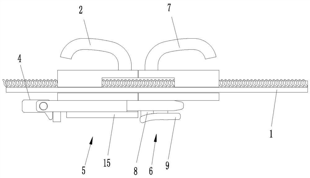
[0031] Such as Figure 1-4 As shown, the locking block is the second slider 7, the second locking unit 6 includes a first limiting plate 8 and a second limiting plate 9, and the first limiting plate 8 is located inside the zipper tape 1 perpendicular to the second slider 7 The surface of the second limiting plate 9 is arranged on the end of the first limiting plate 8 away from the second slider 7, and the first limiting plate 8, the second limiting plate 9 and the second slider 7 are located on the inner side of the zipper tape 1 Part of the I-shaped locking piece is formed, and the two sides of the I-shaped locking piece form limiting grooves.
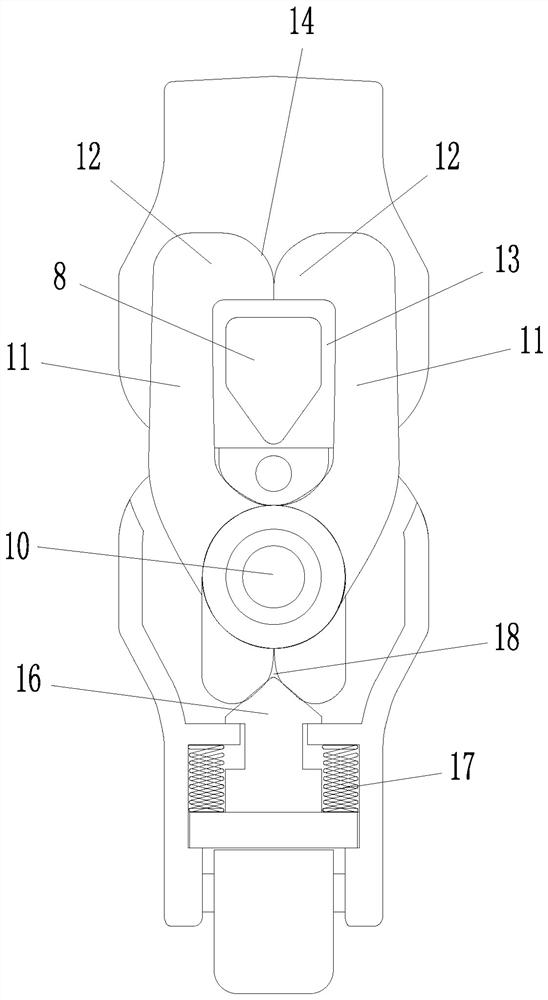
[0032] The first locking unit 5 includes an elastic caliper. The elastic caliper is provided with a lower cover 15 on the side away from the first slider 2. The elastic caliper includes a shaft 10, a torsion spring and two pliers arms 11. The two pliers arms 11 are movable locks. , the shaft 10 is set on the surface of the first slid...
Embodiment 2
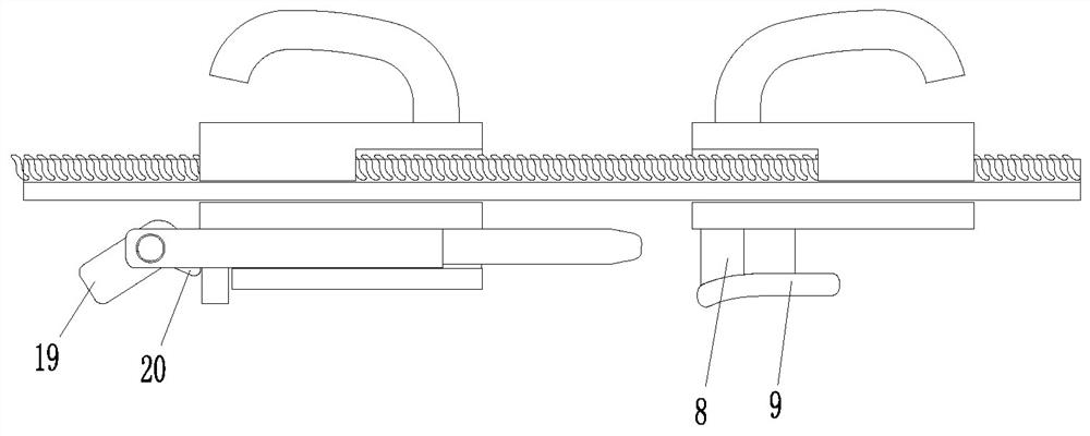
[0037] Such as Figure 5 , 6 As shown, the difference between Embodiment 2 and Embodiment 1 lies in the difference of the unlocking unit. In this embodiment, the unlocking unit includes two unlocking buttons 4 respectively arranged on the left and right sides of the elastic caliper. The unlocking button 4 is arranged on the shaft 10 away from On one side of the blocking arm 12, the unlock button 4 is rotationally connected to the first slider 2 near the end of the blocking arm 12, and the inner walls of the two unlocking buttons 4 are respectively arranged opposite to the outer walls of the parts of the two pliers arms 11 away from the blocking arm 12. The outer walls of the two unlocking buttons 4 protrude to the outside of the first slider 2 and can drive the two pliers arms 11 to rotate around the shaft 10 to open the clamping cavity 13 after receiving side pressure. A limit protrusion is provided on the end of the unlock button 4 away from the blocking arm 12 , and a limi...
Embodiment 3
[0040] Such as Figure 7-9 As shown, the locking block is the second slider 7, the second locking unit 6 includes a first limiting plate 8 and a second limiting plate 9, and the first limiting plate 8 is located inside the zipper tape 1 perpendicular to the second slider 7 The surface of the second limiting plate 9 is arranged on the end of the first limiting plate 8 away from the second slider 7, and the first limiting plate 8, the second limiting plate 9 and the second slider 7 are located on the inner side of the zipper tape 1 Part of the I-shaped locking piece is formed, and the two sides of the I-shaped locking piece form limiting grooves.
[0041] The first locking unit 5 includes a mounting cover 21 fixedly connected to the first slider 2, a first seesaw 22 disposed in the mounting cover 21, a second seesaw 23 disposed in the mounting cover 21, and a locking driver. The driving part is a magnet 24, and the installation cover 21 is provided with an insertion slot 25 nea...
PUM
 Abstract
Description
Claims
Application Information
 - R&D
- Intellectual Property
- Life Sciences
- Materials
- Tech Scout
- Unparalleled Data Quality
- Higher Quality Content
- 60% Fewer Hallucinations
Browse by: Latest US Patents, China's latest patents, Technical Efficacy Thesaurus, Application Domain, Technology Topic, Popular Technical Reports.
© 2025 PatSnap. All rights reserved.Legal|Privacy policy|Modern Slavery Act Transparency Statement|Sitemap|About US| Contact US: help@patsnap.com


