Conversion lens, interchangeable lens, and image capturing apparatus
A technology for converting lenses and lenses, applied in installation, instruments, optics, etc., can solve problems such as difficult to convert lenses
- Summary
- Abstract
- Description
- Claims
- Application Information
AI Technical Summary
Problems solved by technology
Method used
Image

Examples
no. 1 example
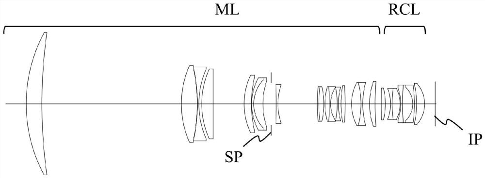
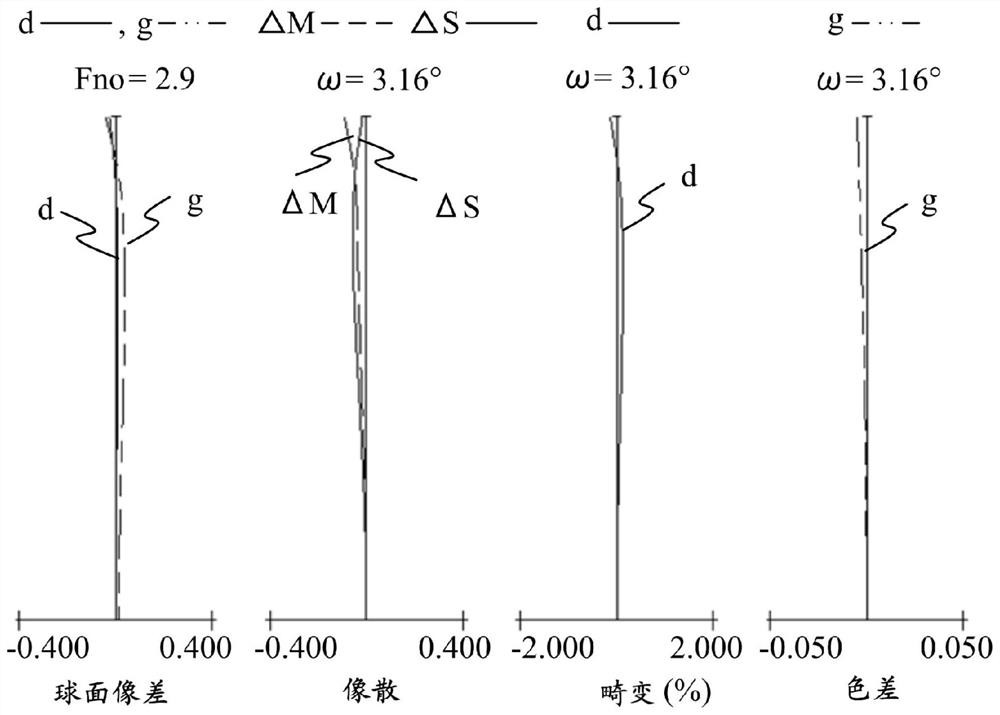
[0119] image 3 is a sectional view of the conversion lens RCL according to the first embodiment. Figure 4 is an aberration diagram of the conversion lens RCL according to the first embodiment when focusing on an object at infinity when disposed on the image side of the main lens ML.
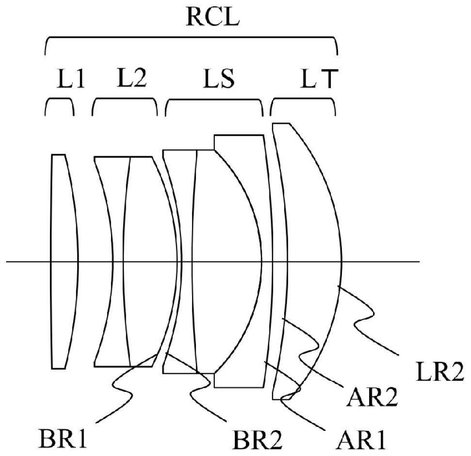
[0120] In conversion lens RCL according to the first embodiment, first lens element L1 is a positive single lens disposed closest to the object side in conversion lens RCL. The second lens element L2 is a cemented lens in which two lenses of a negative lens and a positive lens are sequentially cemented from the object side to the image side. Lens element LT is a positive single lens disposed closest to the image side in conversion lens RCL, and lens element LS is a cemented lens in which three lenses of a negative lens, a positive lens, and a negative lens are sequentially cemented from the object side.
no. 2 example
[0122] Figure 5 is a sectional view of the conversion lens RCL according to the second embodiment. Image 6 is an aberration diagram of the conversion lens RCL according to the second embodiment when focusing on an object at infinity when disposed on the image side of the main lens ML.
[0123] In conversion lens RCL according to the second embodiment, first lens element L1 is a positive single lens disposed closest to the object side in conversion lens RCL. The second lens element L2 is a cemented lens in which two lenses of a negative lens and a positive lens are sequentially cemented from the object side to the image side. Lens element LT is a positive single lens disposed closest to the image side in conversion lens RCL, and lens element LS is a cemented lens in which three lenses of a negative lens, a positive lens, and a negative lens are sequentially cemented from the object side.
no. 3 example
[0125] Figure 7 is a sectional view of the conversion lens RCL according to the third embodiment. Figure 8 is an aberration diagram of the conversion lens RCL according to the third embodiment when focusing on an object at infinity when disposed on the image side of the main lens ML.
[0126] In conversion lens RCL according to the third embodiment, first lens element L1 is a positive single lens disposed closest to the object side in conversion lens RCL. The second lens element L2 is a cemented lens in which three lenses of a negative lens, a positive lens, and a negative lens are sequentially cemented from the object side to the image side. Lens element LT is a positive single lens disposed closest to the image side in conversion lens RCL, and lens element LS is a cemented lens in which two lenses of a positive lens and a negative lens are sequentially cemented from the object side.
PUM
 Abstract
Description
Claims
Application Information
 - R&D Engineer
- R&D Manager
- IP Professional
- Industry Leading Data Capabilities
- Powerful AI technology
- Patent DNA Extraction
Browse by: Latest US Patents, China's latest patents, Technical Efficacy Thesaurus, Application Domain, Technology Topic.
© 2024 PatSnap. All rights reserved.Legal|Privacy policy|Modern Slavery Act Transparency Statement|Sitemap