Camera and laser radar joint calibration method based on L-shaped calibration plate

A laser radar and joint calibration technology, which is applied in the field of camera and laser radar joint calibration, can solve problems such as inaccurate acquisition, increased matching error, and reduced camera and laser radar external parameter accuracy.

Pending Publication Date: 2021-05-18
福州视驰科技有限公司
View PDF0 Cites 10 Cited by
  • Summary
  • Abstract
  • Description
  • Claims
  • Application Information

AI Technical Summary

Problems solved by technology
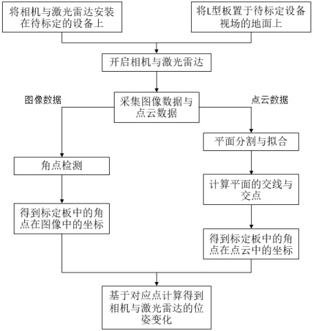
However, for low-beam lidar, due to the sparsity of the point cloud, it cannot accurately obtain the specific position of the feature points of the calibration plate in space, resulting in an increase in the matching error between the feature points in the image and the corresponding points in space, thereby reducing the Accuracy of camera and lidar extrinsic calibration

Method used


Image

  • Camera and laser radar joint calibration method based on L-shaped calibration plate
  • Camera and laser radar joint calibration method based on L-shaped calibration plate
  • Camera and laser radar joint calibration method based on L-shaped calibration plate

Examples


Embodiment Construction

[0049] The technical solution of the present invention will be specifically described below in conjunction with the accompanying drawings.

[0050] It should be pointed out that the following detailed description is exemplary and is intended to provide further explanation to the present application. Unless defined otherwise, all technical and scientific terms used herein have the same meaning as commonly understood by one of ordinary skill in the art to which this application belongs.

[0051] It should be noted that the terminology used here is only for describing specific implementations, and is not intended to limit the exemplary implementations according to the present application. As used herein, unless the context clearly dictates otherwise, the singular is intended to include the plural, and it should also be understood that when the terms "comprising" and / or "comprising" are used in this specification, they mean There are features, steps, operations, means, components...


PUM


Abstract

The invention relates to a camera and laser radar joint calibration method based on an L-shaped calibration plate. The method includes: firstly, installing a camera and a laser radar on to-be-calibrated equipment; secondly, placing the L-shaped calibration plate on the ground in the field of view of equipment to be calibrated; starting a camera and a laser radar, carrying out data collection, and obtaining an image containing the L-shaped calibration plate and point cloud data; performing angular point detection on the image data to obtain pixel coordinates of feature angular points on two planes of the L-shaped calibration plate; performing plane segmentation and fitting on the point cloud data to obtain an equation of two planes of the L-shaped calibration plate, and further obtaining coordinates of feature angular points on the planes in a laser radar coordinate system through geometric information; and finally, on the basis of the pixel coordinates of the detected angular points and the coordinates in the laser radar coordinate system, calculating and obtaining pose changes of the camera and the laser radar. According to the method, the position of the angular point feature in the point cloud data can be accurately obtained, and the accuracy of joint calibration of the camera and the laser radar is greatly improved.

Description

technical field [0001] The invention relates to the joint calibration of a camera and a laser radar in the calibration field, in particular to a method for joint calibration of a camera and a laser radar based on an L-shaped calibration plate. Background technique [0002] Autonomous vehicles use various sensors to perceive the environment. In order to achieve high-quality perception in complex environments, it is necessary to fuse a variety of different sensor data to achieve more comprehensive perception. In autonomous driving systems, the most commonly used sensors are RGB cameras and multi-line lidar. RGB cameras can obtain high-resolution color and texture information, but cannot obtain high-precision depth information from image data. According to the time difference between emitting and receiving laser light, laser radar provides accurate distance and azimuth information of the detected point, and can work well at night. However, laser radar does not provide color in...

Claims


Application Information

Patent Timeline
Patent Type & Authority Applications(China)
IPC IPC(8): G06T7/80G06F17/16
CPCG06F17/16G06T2207/10028G06T2207/30244G06T7/85
Inventor 刘思宁吴林煌
Owner 福州视驰科技有限公司
Why Eureka
Try Eureka