A cylindrical hybrid magnetic coupling

A magnetic coupling and coupling technology, applied in the direction of permanent magnet clutch/brake, asynchronous inductive clutch/brake, electric brake/clutch, etc., can solve the problem of unadjustable coupling and achieve large load torque , Solve the effect of switching asynchronous working conditions and realizing the effect of synchronous to asynchronous effect

Active Publication Date: 2021-10-26
HEFEI UNIV OF TECH
View PDF10 Cites 0 Cited by
  • Summary
  • Abstract
  • Description
  • Claims
  • Application Information

AI Technical Summary

Problems solved by technology

[0003] In order to solve the technical problem that the existing coupling cannot be adjusted during the synchronization process, the present invention provides a cylindrical hybrid magnetic coupling

Method used


Image

  • A cylindrical hybrid magnetic coupling
  • A cylindrical hybrid magnetic coupling
  • A cylindrical hybrid magnetic coupling

Examples


Embodiment 1

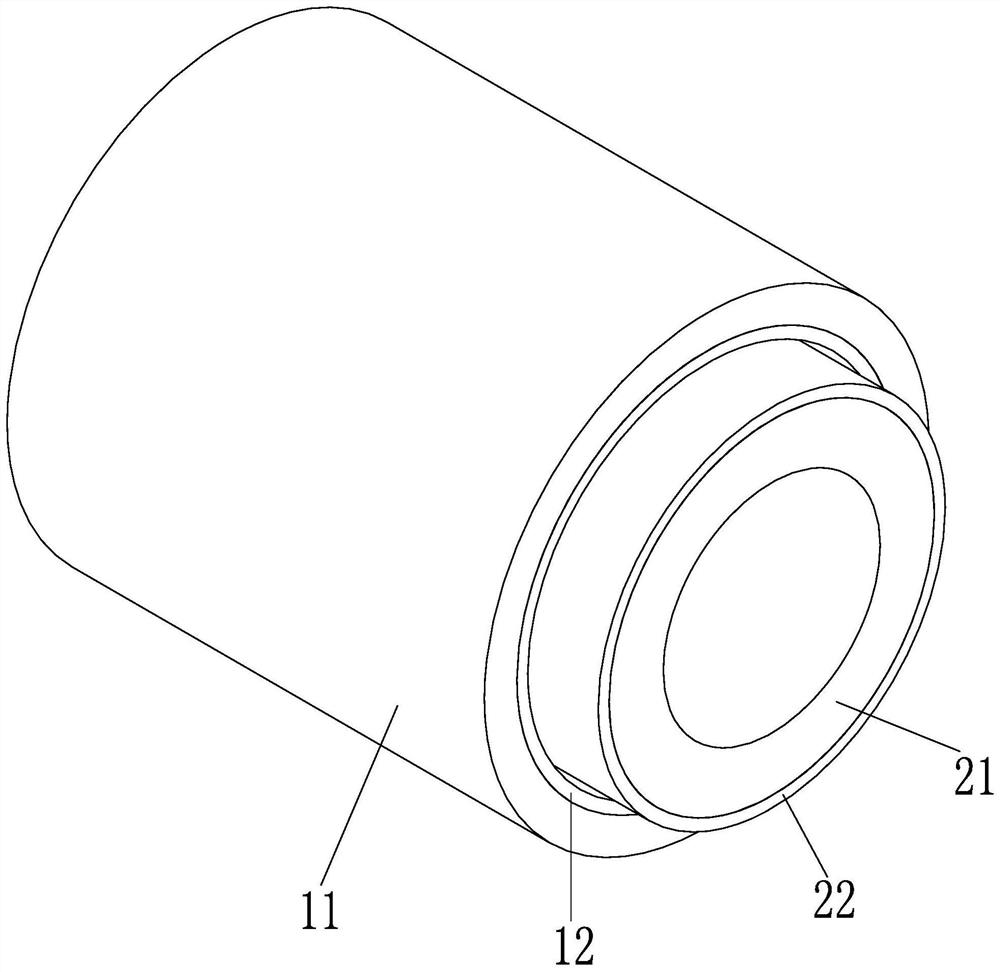
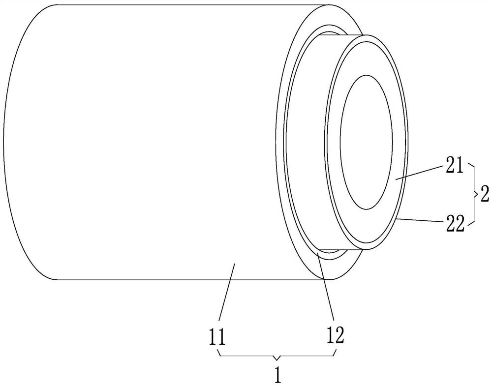
[0033] see figure 1 with figure 2 , this embodiment provides a cylindrical hybrid magnetic coupling, which includes a cylindrical structure 1 and a cylindrical structure 2 . The coupling is a cylindrical coupling, and the first cylindrical structure 1 and the second cylindrical structure 2 are the active part and the driven part of the coupling. These two cylindrical structures can be movably installed through other structures (such as the casing of the shaft coupling device), so as to ensure that no direct contact occurs between the two cylindrical structures, thereby realizing the combined effect of the driving and driven shafts.

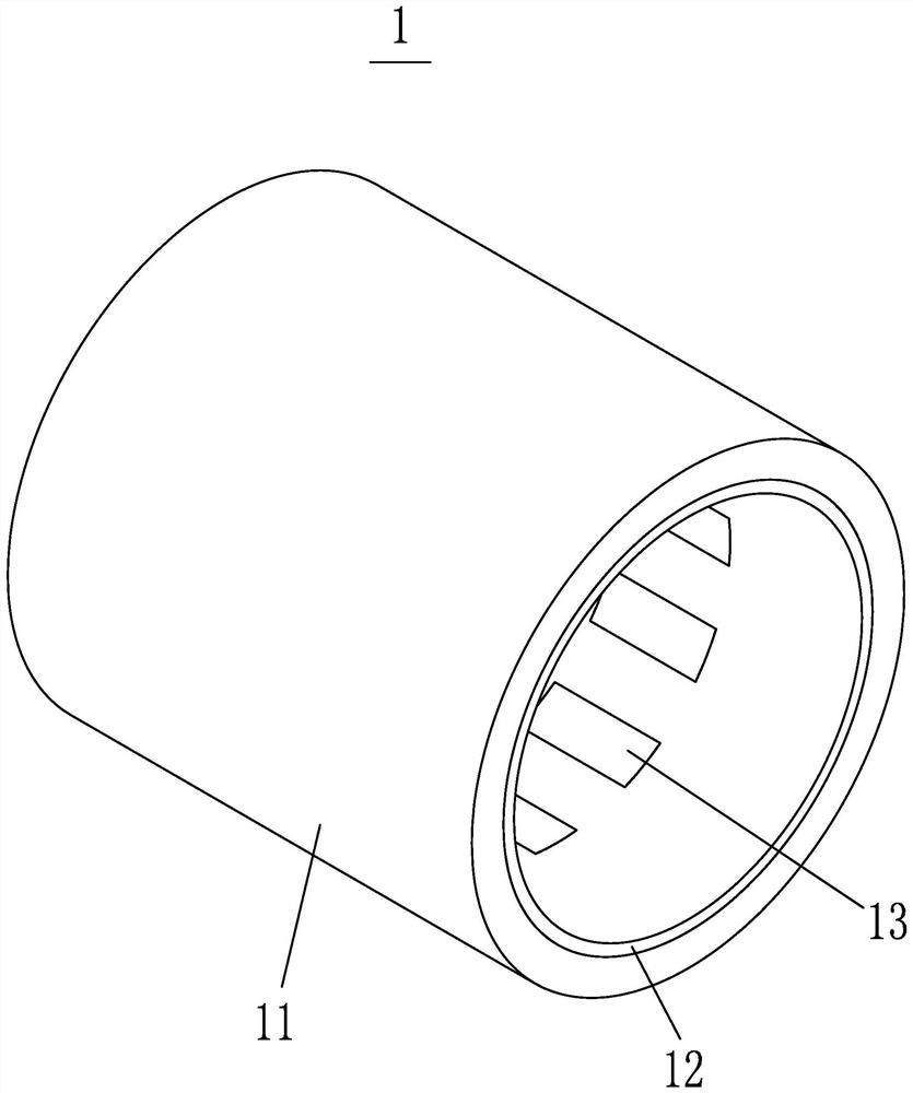
[0034] see image 3 , The cylindrical structure 1 includes an outer cylinder 11 , a mounting cylinder 12 and a plurality of magnets 13 . The outer cylinder 11 is arranged coaxially with the first installation cylinder 12 , and the first installation cylinder 12 is located in the outer cylinder 11 and connected with the outer cylinder 11 . A p...

Embodiment 2

[0043] This embodiment provides a cylindrical hybrid magnetic coupling, which is similar to the coupling in Embodiment 1, the difference is that the outer cylinder 11 and the installation cylinder 12 are integrally formed, and the inner cylinder 21 and the installation cylinder two 22 integrally formed. In this way, when the first magnet 13 or the second magnet 23 is installed, it is only necessary to directly install the magnets on the corresponding installation barrels, and the installation is very convenient. At the same time, in order to be able to generate eddy currents, the installation cylinder part can be made of copper material, while the outer cylinder 11 or inner cylinder 21 can be made of other materials, and an integrally formed material can be used for transition between the two, so that the two are connected more closely.

Embodiment 3

[0045] This embodiment provides a cylindrical hybrid magnetic coupling, which is based on Embodiment 1 with a housing added. Wherein, the cylindrical structure one 1 and the cylindrical structure two 2 are both movably installed in the casing. The casing can be the casing of the existing coupling, and the difference between the coupling of this embodiment and the existing coupling lies in the structure inside the casing. In this way, the housing can play a positioning role, and can also play a protective role, which can prevent dust from entering, and can also prevent other objects from colliding with the inner structure of the coupling.


PUM


Abstract

The invention discloses a cylindrical hybrid magnetic coupling. The shaft coupling includes a cylindrical structure 1 and a cylindrical structure 2. The cylindrical structure 1 includes an outer cylinder, a mounting cylinder 1 and a plurality of magnets 1, and the cylindrical structure 2 includes an inner cylinder, a mounting cylinder 2 and a plurality of magnets 2. The installation cylinder one is located in the outer cylinder and is connected with the outer cylinder. A plurality of magnets are arranged around the central axis of the installation cylinder one and installed on the installation cylinder one. The second installation cylinder is located outside the inner cylinder and connected with the inner cylinder. A plurality of second magnets are arranged around the central axis of the second installation cylinder and installed on the second installation cylinder. There are two working conditions in the present invention. When the first magnet and the second magnet partially overlap in the radial space, the first working condition of the present invention is similar to the permanent magnet synchronous coupling; when the first magnet and the second magnet do not overlap in the radial space, this The second working condition of the invention is similar to the permanent magnet eddy current coupling; the present invention can change the magnetic moment by changing the axial relative position of the outer cylinder and the inner cylinder, so as to realize the stable conversion of the working condition during operation.

Description

technical field [0001] The invention relates to a magnetic coupling in the technical field of couplings, in particular to a cylindrical hybrid magnetic coupling. Background technique [0002] Coupling refers to a device that connects two shafts or shafts and rotating parts, and rotates together during the transmission of motion and power, and does not disengage under normal conditions. At the same time, the permanent magnet coupling is also used as a safety device to prevent the connected parts from being subjected to excessive loads and play the role of overload protection. Synchronous permanent magnet eddy current couplings have low utilization rate of magnetic energy and limited torque. However, the eddy current permanent magnet eddy current coupling cannot achieve synchronous coupling, nor can it achieve more accurate speed control. The hybrid coupling can realize the functions of the synchronous permanent magnet eddy current coupling and the eddy current permanent mag...

Claims


Application Information

Patent Timeline
Patent Type & Authority Patents(China)
IPC IPC(8): H02K49/10H02K49/04
CPCH02K49/043H02K49/106
Inventor 郑红梅郑明睿陈科史洪扬殷磊田文立刘志杰
Owner HEFEI UNIV OF TECH
Why Eureka
Try Eureka