Method, device and computer readable medium for beam failure recovery for secondary cell
A technology of fault recovery and secondary cell, applied in the field of communication
- Summary
- Abstract
- Description
- Claims
- Application Information
AI Technical Summary
Problems solved by technology
Method used
Image

Examples
Embodiment Construction
[0050] The principles of the disclosure will now be described with reference to some example embodiments. It should be understood that these embodiments are described only for the purpose of illustration, and to help those skilled in the art to understand and implement the present disclosure, without any limitation to the scope of the present disclosure. The disclosure described herein can be implemented in various ways other than those described below.
[0051] In the following description and claims, unless defined otherwise, all technical and scientific terms used herein have the same meaning as commonly understood by one of ordinary skill in the art to which this disclosure belongs.
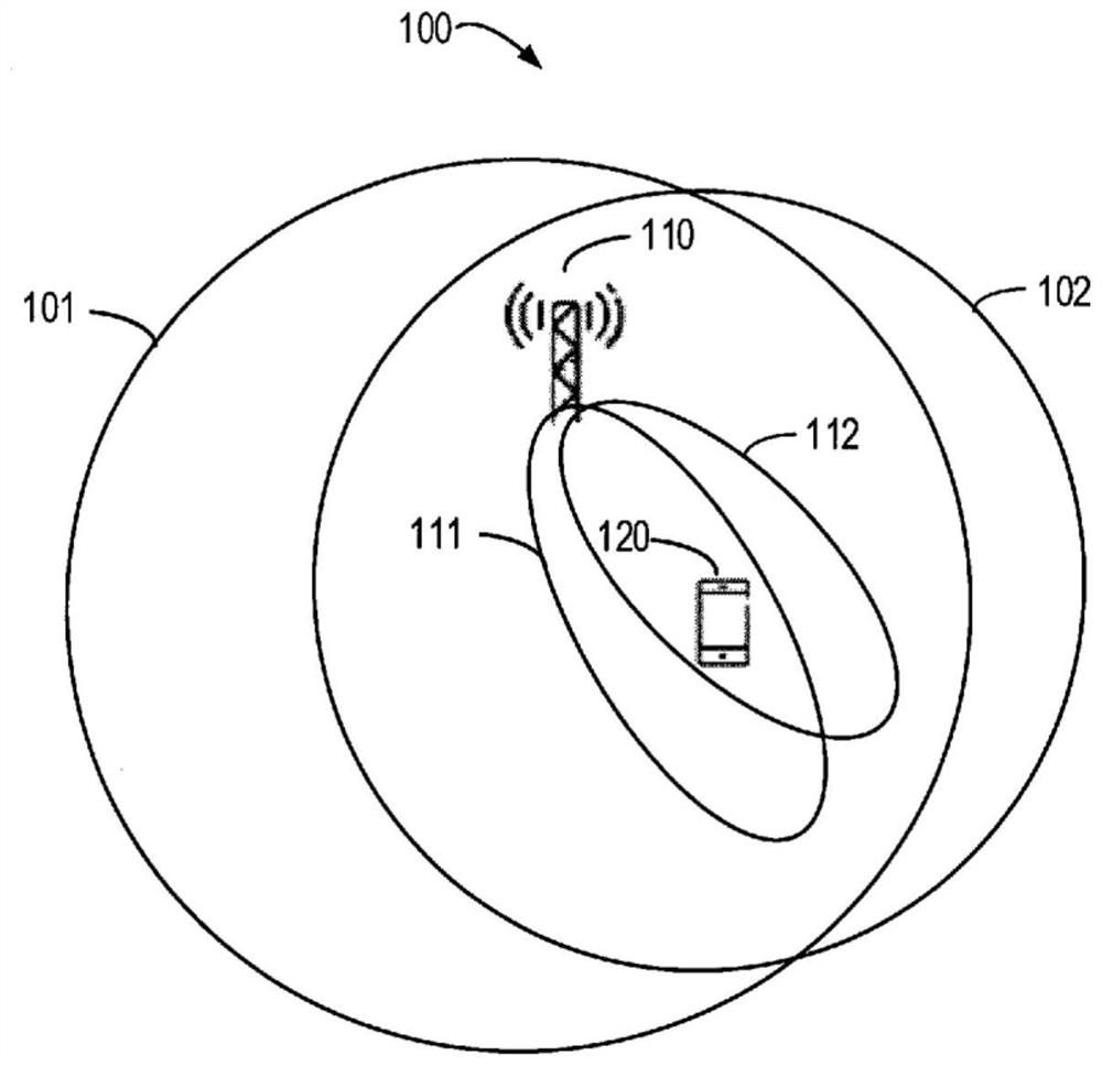
[0052] As used herein, the term "network device" or "base station" (BS) refers to a device capable of providing or hosting a cell or coverage area in which end devices can communicate. Examples of network equipment include, but are not limited to, Node B (NodeB or NB), Evolved NodeB (eNodeB ...
PUM
 Abstract
Description
Claims
Application Information
 - Generate Ideas
- Intellectual Property
- Life Sciences
- Materials
- Tech Scout
- Unparalleled Data Quality
- Higher Quality Content
- 60% Fewer Hallucinations
Browse by: Latest US Patents, China's latest patents, Technical Efficacy Thesaurus, Application Domain, Technology Topic, Popular Technical Reports.
© 2025 PatSnap. All rights reserved.Legal|Privacy policy|Modern Slavery Act Transparency Statement|Sitemap|About US| Contact US: help@patsnap.com