Supercharge Your Innovation With Domain-Expert AI Agents!

Thermal printer core

A technology of thermal printers and cores, applied in printing devices, printing, etc., can solve problems such as difficult to reduce paper jam resistance, affect the normal operation of rubber rollers, and function failures, and achieve the effect of eliminating non-returning

Pending Publication Date: 2021-05-28
宁波精芯科技有限公司
View PDF5 Cites 0 Cited by
  • Summary
  • Abstract
  • Description
  • Claims
  • Application Information

AI Technical Summary

Problems solved by technology

But there are the following disadvantages: the bearing moves in the groove to a large extent, which affects the normal operation of the rubber roller
However, in actual use, when the paper jammed into the contact surface between the moving knife and the fixed knife (usually called paper jam), it is difficult to reduce the impact of paper jam on the moving knife due to the sinking of the fixed knife. The resistance of the position will cause the moving knife to fail to retreat, and the function will fail.

Method used


Image

  • Thermal printer core
  • Thermal printer core
  • Thermal printer core

Examples


Embodiment Construction

[0039] The present invention will be further described in detail below in conjunction with the accompanying drawings and embodiments.

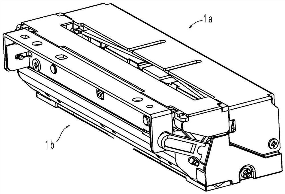
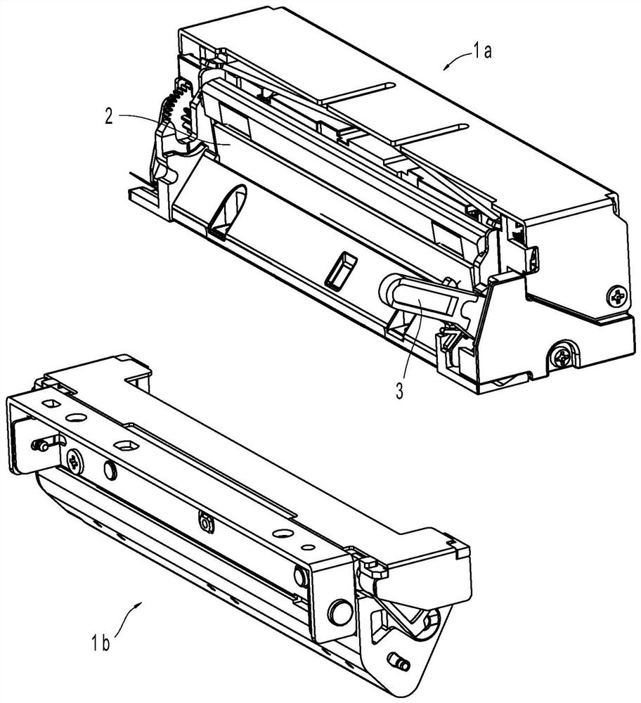
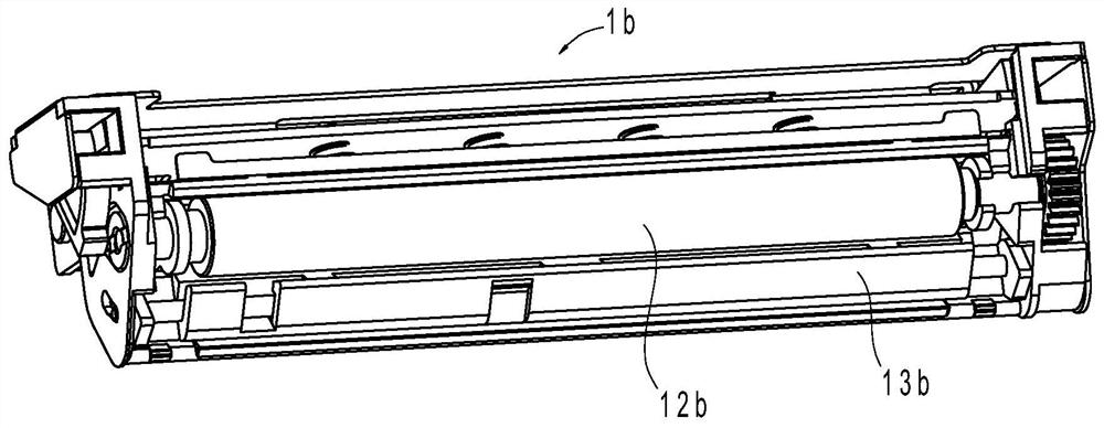
[0040] Such as figure 1 , figure 2 , image 3 As shown, the thermal printer mechanism in this embodiment includes a base frame part and a mounting frame part, combined with image 3 and Figure 4 As shown, the installation frame part includes the installation frame, the rubber roller assembly, the shaft and the rubber roller bracket. The shaft 15b and the rubber roller assembly 12b are rotatably arranged on the installation frame 11b through the rubber roller shaft 122b, and the shaft 15b is arranged on the installation frame 11b and parallel to the rubber roller shaft 122b; Both ends of the roller bracket 13b are extended upwards with supporting parts 14b, and the rubber roller assembly 12b is rotatably arranged on the supporting parts 14b.

[0041] combine Figure 5 and Figure 6As shown, the pedestal part mainly includes a pedestal ...


PUM


Abstract

A thermal printer core comprises a base frame, a mounting frame, a printing head, a moving cutter and a rubber roller assembly, the printing head is arranged on the base frame, the mounting frame is arranged on the base frame through a detaching mechanism, the moving cutter is movably arranged on the base frame, and at least one end of the moving cutter is provided with a rack part. The thermal printer core is characterized in that the detaching mechanism comprises a rotating shaft, a handle, a reset piece and a shaft rod, and a sliding block capable of driving an output gear to rotate is elastically arranged on the base frame. The stressed sliding block moves to push the output gear to rotate, and finally the moving cutter returns. Even if paper is jammed by the cutter, the moving cutter can still be smoothly driven to return due to the existence of the sliding block.

Description

technical field [0001] The invention relates to a printing device, in particular to a thermal printer core. Background technique [0002] Existing thermal printers generally include a base frame, a motor, a transmission gear assembly, a print head assembly, and a rubber roller that can be rotatably arranged on the base frame. The power input end of the transmission gear assembly meshes with the active output gear of the motor, and the power output The end meshes with the rubber roller gear located at the end of the rubber roller. The rubber roller is used to drive the printing paper to move. There is a paper feeding channel between the rubber roller and the print head assembly. The print head assembly generally includes a print head (TPH for short, Thermal Print Head), print head bracket, compression spring and compression spring supporting frame, the printing head is arranged on the printing head bracket, and the two ends of the compression spring supporting frame are arran...

Claims


Application Information

Patent Timeline
Patent Type & Authority Applications(China)
IPC IPC(8): B41J2/32B41J11/00B41J11/70
CPCB41J2/32B41J11/006B41J11/70
Inventor 蒋文柏林超艺王生辉
Owner 宁波精芯科技有限公司
Features
  • R&D
  • Intellectual Property
  • Life Sciences
  • Materials
  • Tech Scout
  • Unparalleled Data Quality
  • Higher Quality Content
  • 60% Fewer Hallucinations
Learn More