Supercharge Your Innovation With Domain-Expert AI Agents!

Telescopic supporting structure

A technology of telescopic support and telescopic mechanism, which is applied in the direction of building construction, residential construction, casters, etc., can solve the problems of heavy workload, high labor cost, and long time consumption, and achieve long service life, stable structure, and low cost. Effect

Pending Publication Date: 2021-05-28
广州国盛高新科技发展有限公司
View PDF0 Cites 0 Cited by
  • Summary
  • Abstract
  • Description
  • Claims
  • Application Information

AI Technical Summary

Problems solved by technology

The problems with the construction or dismantling of such large temporary buildings are that the construction and dismantling of large temporary buildings requires a lot of work, time-consuming, and high labor costs.

Method used


Image

  • Telescopic supporting structure
  • Telescopic supporting structure

Examples


Embodiment 1

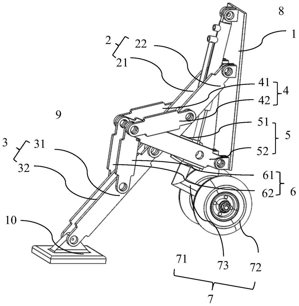
[0038] Such as figure 1 As shown, a telescopic support structure in a preferred embodiment of the present invention includes a base plate 1 , a support rod, a reinforcing rod and a hydraulic column 8 .

[0039] The support rods include a first left support rod 21 and a first right support rod 22 arranged in parallel, a second left support rod 31 and a second right support rod 32 arranged in parallel, and the first left support rod 21 and the second right support rod 32 which are hinged to each other. The two left support rods 31 are arranged on the left side of the hydraulic column 8, and the mutually hinged first right support rod 22 and the second right support rod 32 are arranged on the right side of the hydraulic column 8;

[0040] The reinforcing bar comprises a first left reinforcing bar 41 and a first right reinforcing bar 42 arranged in parallel, a second left reinforcing bar 51 and a second right reinforcing bar 52 arranged in parallel, and a third left reinforcing ba...

Embodiment 2

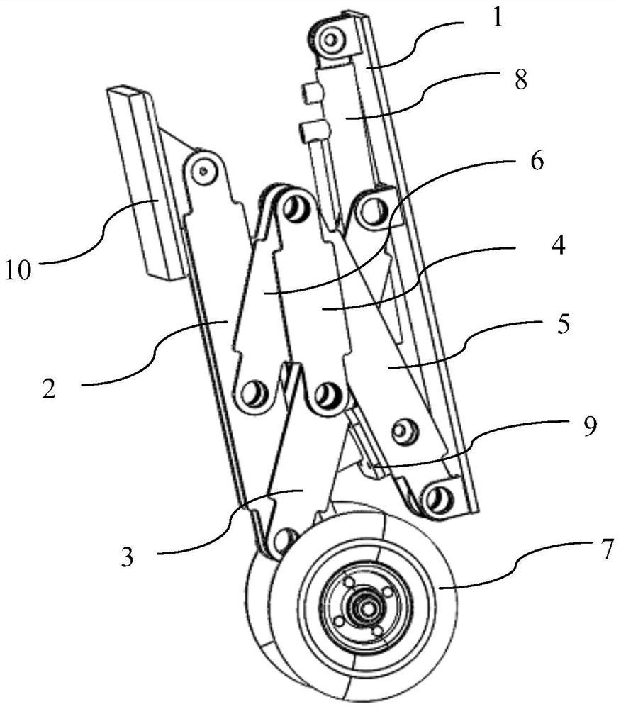
[0048] A telescopic supporting structure, comprising a base plate 1, a supporting rod, a reinforcing rod and a telescopic mechanism. The support rod includes a first support rod 2 and a second support rod 3, one end of the first support rod 2 is hinged on the base plate, and the other end of the first support rod 2 is hinged with the second support rod 3; A reinforcement rod 4, a second reinforcement rod 5 and a third reinforcement rod 6, the other end of the first reinforcement rod 4 is hinged to the first support rod 2, the other end of the second reinforcement rod 5 is hinged to the base plate 1, and the third reinforcement rod 6 is in addition One end is hinged to the second support rod 3; one end of the telescopic mechanism is connected to the base plate, and the other end is connected to the second support rod 3.

[0049] The lower part of the second reinforcing rod 5 is provided with a limiting plate 9, the lower end of the hydraulic column 8 is connected to the limitin...


PUM


Abstract

The invention relates to the technical field of supporting devices, and discloses a telescopic supporting structure which comprises a base plate, supporting rods, reinforcing rods and a telescopic mechanism. The supporting rods comprise a first supporting rod and a second supporting rod, one end of the first supporting rod is hinged to the base plate, and the other end of the first supporting rod is hinged to the second supporting rod. The reinforcing rods comprise a first reinforcing rod, a second reinforcing rod and a third reinforcing rod, one ends of the first reinforcing rod, the second reinforcing rod and the third reinforcing rod are hinged together, the other end of the first reinforcing rod is hinged to the first supporting rod, the other end of the second reinforcing rod is hinged to the base plate, and the other end of the third reinforcing rod is hinged to the second supporting rod. One end of the telescopic mechanism is connected to the base plate, and the other end is connected with the second supporting rod. The telescopic supporting structure has the beneficial effects that through the structural combination of the base plate, the supporting rods, the reinforcing rods and the telescopic mechanism and the connection design of the linkage mechanism, the telescopic supporting structure capable of being automatically folded and unfolded is achieved. The frame structure combination is stable, the service life is long, automatic control can be achieved, the structural design is exquisite, and the application range is wide.

Description

technical field [0001] The invention relates to the technical field of support devices, in particular to a telescopic support structure. Background technique [0002] With the vigorous development of ecotourism, more and more people turn to the natural landscape with beautiful environment when choosing tourist destinations, and even prefer the wild natural environment with less traces of human activities. In order to meet people's increasing demand for quality tourism, many detachable houses have emerged in the prior art. [0003] One type of house mainly adopts factory prefabricated enclosure structures, roofs, frames, etc., and often uses three-way, four-way and other connectors to connect beams and columns. This structure uses friction to tie beams or columns together. If If the connection is too loose, it is easy to fall off and shake; if the connection is too tight, it is not easy to disassemble. [0004] The other is a tent-style house that is light in weight and eas...

Claims


Application Information

Patent Timeline
IPC IPC(8): E04B1/343E04H1/02B60B33/06
CPCB60B33/06B60B33/066E04B1/343E04H1/02
Inventor 尹国英黄树文
Owner 广州国盛高新科技发展有限公司
Features
  • R&D
  • Intellectual Property
  • Life Sciences
  • Materials
  • Tech Scout
  • Unparalleled Data Quality
  • Higher Quality Content
  • 60% Fewer Hallucinations
Learn More