Method and device for false closing test of power module bypass switch of flexible DC converter valve
A flexible DC and power module technology, applied in the direction of circuit breaker testing, etc., can solve the problem of damage to the power module of the flexible DC converter valve
- Summary
- Abstract
- Description
- Claims
- Application Information
AI Technical Summary
Problems solved by technology
Method used
Image
Examples
Embodiment 1
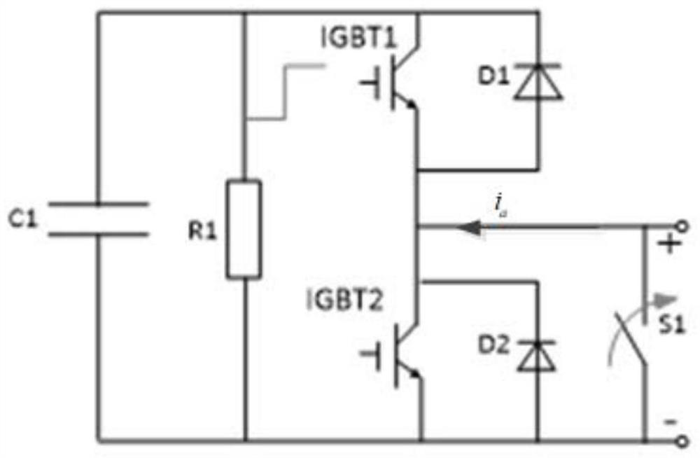
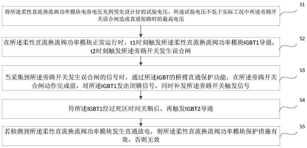
[0028] see figure 2 , image 3 , figure 2 It is the schematic diagram of the bypass switch misconnection test of the flexible DC converter valve power module, where IGBT1 and IGBT2 are insulated gate bipolar transistors, S1 is the bypass switch, R1 is the voltage equalizing resistor, D1 and D2 are diodes, and C1 for the capacitor, image 3 The flow diagram of the test method for the bypass switch of the flexible DC converter valve power module bypass switch provided by the embodiment of the present invention includes:
[0029] S1. Charge the voltage of the capacitor C1 of the flexible DC converter valve power module to a pre-designed test voltage, which is not lower than the highest voltage when the bypass switch is mistakenly closed in the actual working condition and causes a direct short circuit .
[0030] S2. When the power module of the flexible DC converter valve is running normally, trigger the conduction of the IGBT1 of the flexible DC converter valve power modul...
Embodiment 2
[0039] An embodiment of the present invention provides a flexible DC converter valve power module bypass switch mis-closing test device including a controller, the controller is configured to:
[0040] Charging the capacitor voltage of the flexible DC converter valve power module to a pre-designed test voltage, the test voltage is not lower than the highest voltage when the bypass switch is closed by mistake in actual working conditions and causes a direct short circuit;
[0041] When the flexible DC converter valve power module is operating normally, the flexible DC converter valve power module IGBT1 is triggered to be turned on at time t1, and the bypass switch is triggered to be closed incorrectly at time t2;
[0042] When the signal of false closing of the bypass switch is collected, through the bridge arm through protection function of the IGBT1, before the closing action of the bypass switch is completed, a blocking signal is sent to the IGBT1, and a reissued The bypass sw...
PUM
 Abstract
Description
Claims
Application Information
 - R&D
- Intellectual Property
- Life Sciences
- Materials
- Tech Scout
- Unparalleled Data Quality
- Higher Quality Content
- 60% Fewer Hallucinations
Browse by: Latest US Patents, China's latest patents, Technical Efficacy Thesaurus, Application Domain, Technology Topic, Popular Technical Reports.
© 2025 PatSnap. All rights reserved.Legal|Privacy policy|Modern Slavery Act Transparency Statement|Sitemap|About US| Contact US: help@patsnap.com


