Control method of milling cutter type board dividing machine system

A control method and a technology of a splitter, which are applied in the manufacturing of printed circuits, processing of insulating substrates/layers, electrical components, etc., can solve the problems of time-consuming teaching methods, scrapped PCB boards, troubles, etc., and achieve debugging and operation. The effect of intelligence, machine capacity optimization, and utilization efficiency optimization

Pending Publication Date: 2021-05-28
广东千博瑞智能科技有限公司
View PDF0 Cites 0 Cited by
  • Summary
  • Abstract
  • Description
  • Claims
  • Application Information

AI Technical Summary

Problems solved by technology

[0002] At present, the main method of cutting PCB boards on the market is that the staff first observe and determine the position where the PCB board needs to be cut, and then put it in the splitting fixture, and move the XY axis to move the cross center of the camera on the splitting machine. Go to the starting point of the position to be cut, press the button or mouse to confirm the starting point, and then move to the end point again to confirm, the software will automatically generate a cutting trajectory line, if it is an arc or a polyline, you need to move the XY axis multiple times Confirm the starting point, middle point and end point, and after confirming in turn, the system will generate the cutting trajectory path. When teaching two MARK points, the technician needs to follow the real object and then use the camera to teach the two diagonal points of the PCB board And confirmation, this method needs to be confirmed point by point by moving the camera to the position to be cut. Due to the limitation of the field of view of the machine camera and the similarity of the cutting position of the PCB itself, it is easy for technicians to make mistakes and omit setting the cutting position. The starting point and the end point will lead to the scrapping of the PCB board. In addition, the teaching method of the cutting path is time-consuming and troublesome. Therefore, we propose a control method for the milling cutter type board splitting machine system.

Method used


Image

  • Control method of milling cutter type board dividing machine system
  • Control method of milling cutter type board dividing machine system
  • Control method of milling cutter type board dividing machine system

Examples


Embodiment Construction

[0034] The following will clearly and completely describe the technical solutions in the embodiments of the present invention with reference to the accompanying drawings in the embodiments of the present invention. Obviously, the described embodiments are only some, not all, embodiments of the present invention. Based on the embodiments of the present invention, all other embodiments obtained by persons of ordinary skill in the art without making creative efforts belong to the protection scope of the present invention.

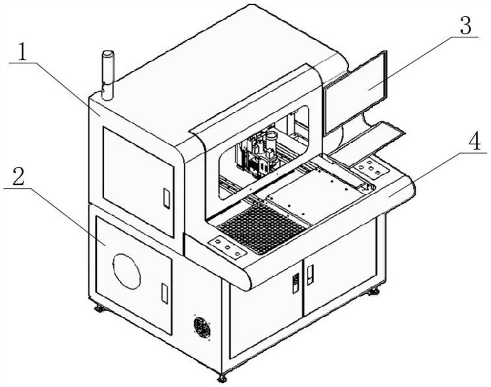
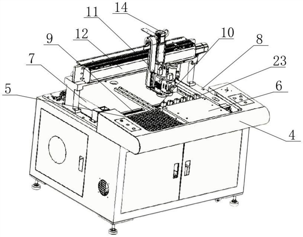
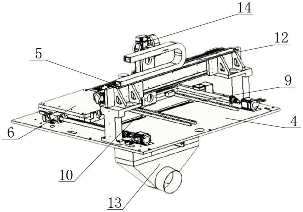
[0035] see Figure 1-10 , the present invention provides a technical solution: a control method for a milling cutter type splitter system, comprising the following steps:

[0036] S1: Place the product, put the product into the corresponding board fixture, move the XY axis to confirm the reference point in the upper left corner of the board, then input the length and width of the product, and click on the puzzle;

[0037] S2: Image collection, the CCD on the ...


PUM


Abstract

The invention discloses a control method of a milling cutter type board dividing machine system. The control method comprises the following eight basic operation steps of product placing, image collecting, precise positioning, cutting point selecting, cutting track adding, program storing, track modifying and cutting completing. The control method of the milling cutter type board dividing machine system is as follows. On one hand, when the cutter is worn, the distance of each sinking section can be set to realize the automatic sinking function of the cutter, and meanwhile, when the cutter is broken off abnormally in the use process, the machine performs monitoring through the cutter breaking and height detection sensor and immediately feeds back a signal to the PC terminal, and the PC terminal sends an instruction to stop working, an alarm prompt is made in software for displaying, so that an operator is reminded of checking and replacing, what is ensured is that the descending position of the cutter on the z-axis is consistent after the cutter is replaced every time and the cutter slides down for a small distance, and a PCB and elements at the bottom of a product are prevented from being damaged by cutting.

Description

technical field [0001] The invention relates to the technical field of a milling cutter type splitter, in particular to a control method for a milling cutter type splitter system. Background technique [0002] At present, the main method of cutting PCB boards on the market is that the staff first observe and determine the position where the PCB board needs to be cut, and then put it in the splitting fixture, and move the XY axis to move the cross center of the camera on the splitting machine. Go to the starting point of the position to be cut, press the button or mouse to confirm the starting point, and then move to the end point again to confirm, the software will automatically generate a cutting trajectory line, if it is an arc or a polyline, you need to move the XY axis multiple times Confirm the starting point, middle point and end point, and after confirming in turn, the system will generate the cutting trajectory path. When teaching two MARK points, the technician need...

Claims


Application Information

Patent Timeline
IPC IPC(8): H05K3/00
CPCH05K3/0052
Inventor 胥邦
Owner 广东千博瑞智能科技有限公司
Why Eureka
Try Eureka