
Plate stamping device

A stamping device and plate technology, applied in the field of plate stamping, can solve the problem that the plate is not easy to take out, and achieve the effect of quick disassembly

Pending Publication Date: 2021-06-01
ANHUI UNIV OF SCI & TECH
View PDF0 Cites 3 Cited by
  • Summary
  • Abstract
  • Description
  • Claims
  • Application Information

AI Technical Summary

Problems solved by technology

[0004] The object of the present invention is to provide a sheet metal punching device. By pulling the limiting member, the limiting shaft is drawn out from the limiting groove, and the engaging block is engaged in the engaging groove by rotating the engaging member to fix the limiting member. Take out the upper mold or the lower mold to realize the rapid disassembly of the mold of the stamping device, and lift the supporting piece through the driving part, which solves the problem that the plate is not easy to take out after stamping

Method used


Image

  • Plate stamping device
  • Plate stamping device
  • Plate stamping device

Examples


Embodiment Construction

[0025] The following will clearly and completely describe the technical solutions in the embodiments of the present invention with reference to the accompanying drawings in the embodiments of the present invention. Obviously, the described embodiments are only some, not all, embodiments of the present invention. Based on the embodiments of the present invention, all other embodiments obtained by persons of ordinary skill in the art without creative efforts fall within the protection scope of the present invention.

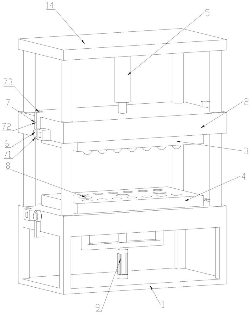
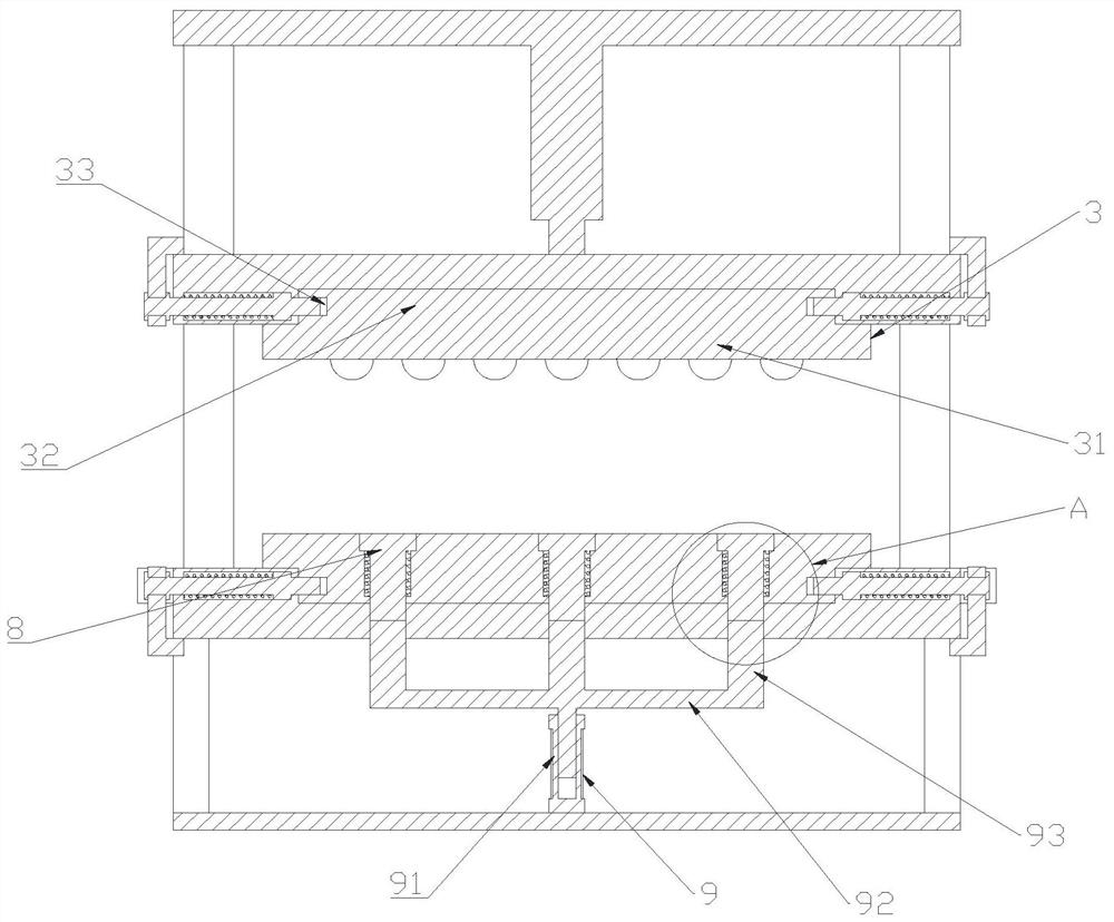
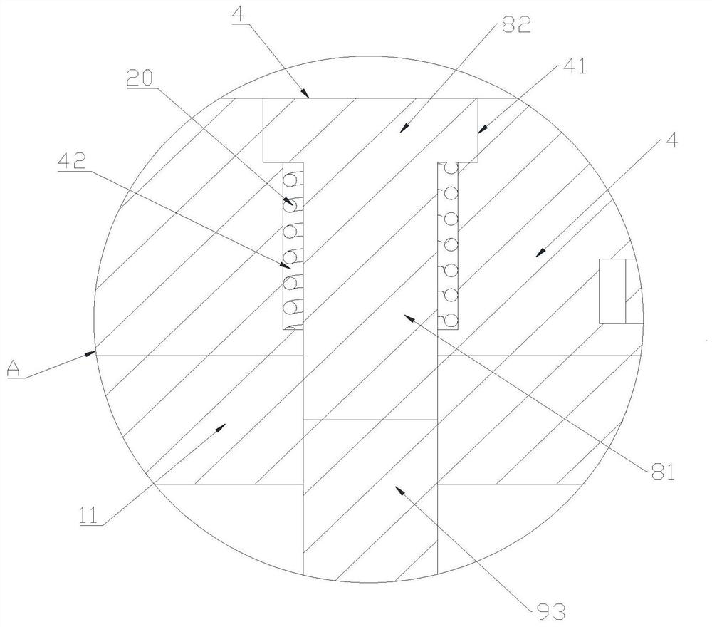
[0026] A sheet metal punching device, the punching device includes a punching platform 1, such as figure 1 , figure 2 and image 3 As shown, on the stamping platform 1, an upper mold fixture 2 is slidably arranged, an upper mold 3 is installed on the upper mold fixture 2, a lower mold 4 is installed on the stamping platform 1, a hydraulic cylinder 5 is fixed on the stamping platform 1, and a hydraulic cylinder 5 is fixed on the stamping platform 1. The output sh...


PUM


Abstract

The invention discloses a plate stamping device. The stamping device comprises a stamping platform, an upper die fixing part is arranged on the stamping platform in a sliding manner, an upper die is installed on the upper die fixing part, a lower die is installed on the stamping platform, a hydraulic cylinder is fixed to the stamping platform, and an output shaft of the hydraulic cylinder is fixed to the upper die fixing part. Limiting pieces which are symmetrically distributed are arranged on the upper die fixing part and the stamping platform in a sliding manner, the limiting pieces on the upper die fixing part are located on the upper die fixing part and clamped on the upper die in a sliding manner to limit the upper die, and the limiting pieces on the stamping platform are located on the stamping platform and clamped on the lower die in a sliding manner to limit the lower die; and supporting pieces distributed in an array manner are installed on the lower die, first elastic pieces are connected between the supporting pieces and the lower die, and a driving piece used for jacking up the supporting pieces is fixed to the stamping platform. According to the stamping device, the supporting pieces are jacked up through the driving piece, and the problem that a plate is not easy to take out after stamping is solved.

Description

technical field [0001] The invention relates to the field of plate stamping, in particular to a plate stamping device. Background technique [0002] Stamping forming refers to the process of applying external force to plates, strips, pipes and profiles by presses and molds to cause plastic deformation or separation, so as to obtain workpieces (stamping parts) of required shape and size. It is processed by stamping. [0003] In the existing sheet metal stamping process, neither the upper mold nor the lower mold can be quickly disassembled, which makes the efficiency of sheet metal stamping low, and there is a problem that the sheet is not easy to take out after stamping. Contents of the invention [0004] The object of the present invention is to provide a sheet metal punching device. By pulling the limiting member, the limiting shaft is drawn out from the limiting groove, and the engaging block is engaged in the engaging groove by rotating the engaging member to fix the l...

Claims


Application Information

Patent Timeline
Patent Type & Authority Applications(China)
IPC IPC(8): B21D22/02B21D37/10B21D37/12B21D37/14B21D45/02
CPCB21D22/02B21D37/10B21D37/12B21D37/14B21D45/02
Inventor 杨唯巍
Owner ANHUI UNIV OF SCI & TECH
Learn More