Oil exploration marking method

A marking method and oil exploration technology, which is applied in the field of oil exploration, can solve problems such as poor leverage for users and increase user burden, and achieve the effects of reducing work load, increasing friction, and facilitating height adjustment

Pending Publication Date: 2021-06-04
陈建和
View PDF0 Cites 0 Cited by
  • Summary
  • Abstract
  • Description
  • Claims
  • Application Information

AI Technical Summary

Problems solved by technology

[0003] However, the pedal mechanism of the soil sampler is often directly locked and fixed with the vertical rod. When the pedal mechanism is fixed too high, it is difficult for the user to take advantage of it. When it is fixed too low, the user may It is necessary to constantly bend down to adjust the position of the pedal mechanism so that deeper sampling and detection can be carried out, thus increasing the burden on the user

Method used


Image

  • Oil exploration marking method
  • Oil exploration marking method
  • Oil exploration marking method

Examples


Embodiment 1

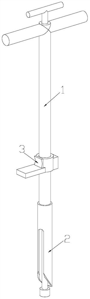
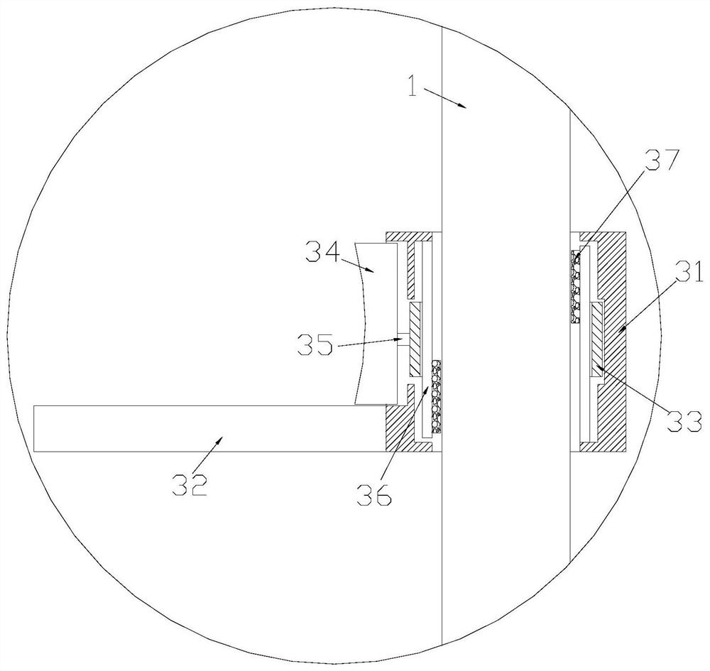
[0029] Such as Figure 1-Figure 3 As shown, the present invention provides a method for marking oil exploration. Its structure includes: a vertical rod 1, a drill bit 2, and a pedal device 3. end, the pedal device 3 is engaged in the middle of the pole 1, and the pedal device 3 is composed of an outer tube 31, a pedal 32, a fastening ring 33, an inner pressure plate 34, a push rod 35, a shrapnel 36, a clip Composed of solid pads 37, the outer sleeve 31 is nested on the pole 1, the pedal 32 is fixed laterally on the outside of the outer sleeve 31, the elastic piece 36 is fixed inside the outer sleeve 31, and the fastening The ring 33 is rotatably engaged inside the outer casing 31 and nested on the elastic piece 36 , and the inner pressure plate 34 is connected to an end of the outer casing 31 close to the pedal 32 through a hinge.

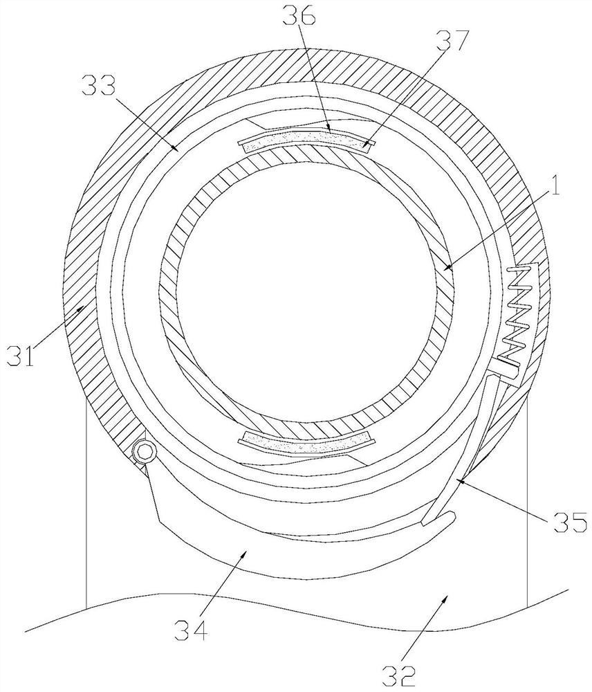
[0030] Such as Figure 4 As shown, the fastening ring 33 is provided with an inner jacking block 331, a jacking pin 332, and a spring 333. There...

Embodiment 2

[0039] Such as Figure 1-Figure 3 As shown, the present invention provides a method for marking oil exploration. Its structure includes: a vertical rod 1, a drill bit 2, and a pedal device 3. end, the pedal device 3 is engaged in the middle of the pole 1, and the pedal device 3 is composed of an outer tube 31, a pedal 32, a fastening ring 33, an inner pressure plate 34, a push rod 35, a shrapnel 36, a clip Composed of solid pads 37, the outer sleeve 31 is nested on the pole 1, the pedal 32 is fixed laterally on the outside of the outer sleeve 31, the elastic piece 36 is fixed inside the outer sleeve 31, and the fastening The ring 33 is rotatably engaged inside the outer casing 31 and nested on the elastic piece 36 , and the inner pressure plate 34 is connected to an end of the outer casing 31 close to the pedal 32 through a hinge.

[0040] Such as Figure 6 As shown, the clamping pad 37 is composed of a friction pad 371 and teeth 372. The friction pad 371 is in the shape of ...


PUM


Abstract

According to an oil exploration marking method, a vertical rod, a drill bit and a pedal device are included, the pedal device is clamped in the middle of the vertical rod, the pedal device is composed of an outer sleeve, a pedal plate, a fastening ring, an inner pressing plate, a push rod, an elastic piece and a clamping and fixing pad, the outer sleeve is nested on the vertical rod, the pedal plate is transversely fixed to the outer portion of the outer sleeve, the elastic piece is fixed in the outer sleeve, the fastening ring is rotationally clamped in the outer sleeve and is nested on the elastic piece, and the inner pressing plate is connected to the end, close to the pedal plate, of the outer sleeve through a hinge. According to the pedal device, the elastic piece is locked and fixed through the fastening ring, and the position, on the vertical rod, of the outer sleeve is fixed, the pedal plate on the outer sleeve can provide leveraging assistance for a user, meanwhile, the inner pressing plate is pressed inwards through the feet of the user, the push rod drives the fastening ring to be unlocked, then attachment of the clamping and fixing pad and the vertical rod is released, the outer sleeve can move on the vertical rod, and the user can conveniently adjust the height.

Description

technical field [0001] The invention relates to the field of petroleum exploration, in particular to a method for marking petroleum exploration. Background technique [0002] The geological method is the basic method of using geological data to find oil and gas fields. The exploration personnel use the sampler to measure and study the geology. At the same time, they can also mark the test area through the holes generated by the sampler when sampling; [0003] However, the pedal mechanism of the soil sampler is often directly locked and fixed with the vertical rod. When the pedal mechanism is fixed too high, it is difficult for the user to take advantage of it. When it is fixed too low, the user may Need to constantly bend down again to adjust the position of pedal mechanism, so that can carry out deeper sampling detection, thus just strengthened the user's burden. Contents of the invention [0004] In view of the above problems, the present invention provides a method for...

Claims


Application Information

Patent Timeline
IPC IPC(8): G01V9/00
CPCG01V9/00
Inventor 陈建和
Owner 陈建和
Why Eureka
Try Eureka