A space-borne dual-band four-channel rotary joint

A rotary joint, dual frequency band technology, applied in the direction of circuits, waveguide devices, electrical components, etc., to achieve the effect of improving stability and reliability, ensuring effective clearance, and high precision

Active Publication Date: 2021-11-05
CHINA ELECTRONIC TECH GRP CORP NO 38 RES INST
View PDF10 Cites 0 Cited by
  • Summary
  • Abstract
  • Description
  • Claims
  • Application Information

AI Technical Summary

Problems solved by technology

[0004] Most of the existing microwave rotary joints are ground-based communication products, and their structures mainly include single-channel, dual-channel and multi-channel forms. In the space environment, multi-channel rotary joint products have certain limitations.

Method used


Image

  • A space-borne dual-band four-channel rotary joint
  • A space-borne dual-band four-channel rotary joint
  • A space-borne dual-band four-channel rotary joint

Examples


Embodiment 1

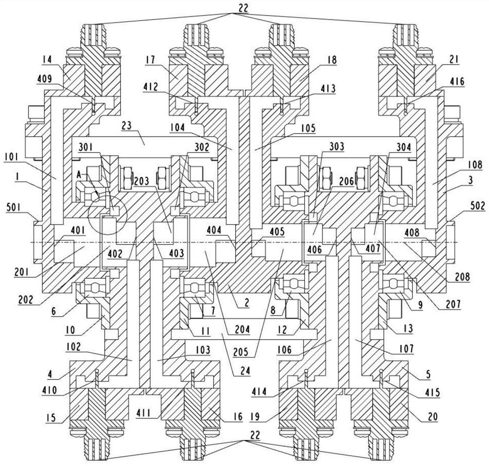
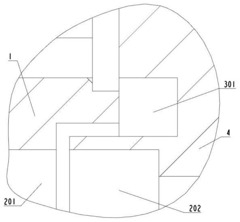
[0042] like figure 1 , figure 2 Distance figure 1 Structure cross-sectional view of the four-channel rotary joint of the star-loaded dual-band; figure 2 for figure 1 A local structure view of the APA (choke).

[0043] The star-loaded double-band four-channel rotary joint of the present invention includes a first single waveguide rotor 1, a first dual waveguide 2, a dual waveguide rotor 3, a second dual wave guide sub-wave 4, a second single waveguide rotor 5, a first bearing 6 , The second bearing 7, the third bearing 8, the fourth bearing 9, the first bearing cover 10, the second bearing cover 11, the third bearing cover 12, the fourth bearing cover 13.

[0044] The first single waveguide rotor 1, the dual waveguide rotor 3 and the second single waveguide rotor 5 are rotor, the first duplex guide 2 and the second dual wave guide 4 being a stator, the rotor And the stator passes through the first bearing 6, the second bearing 7, the third bearing 8, and the fourth bearing 9 suppor...

Embodiment 2

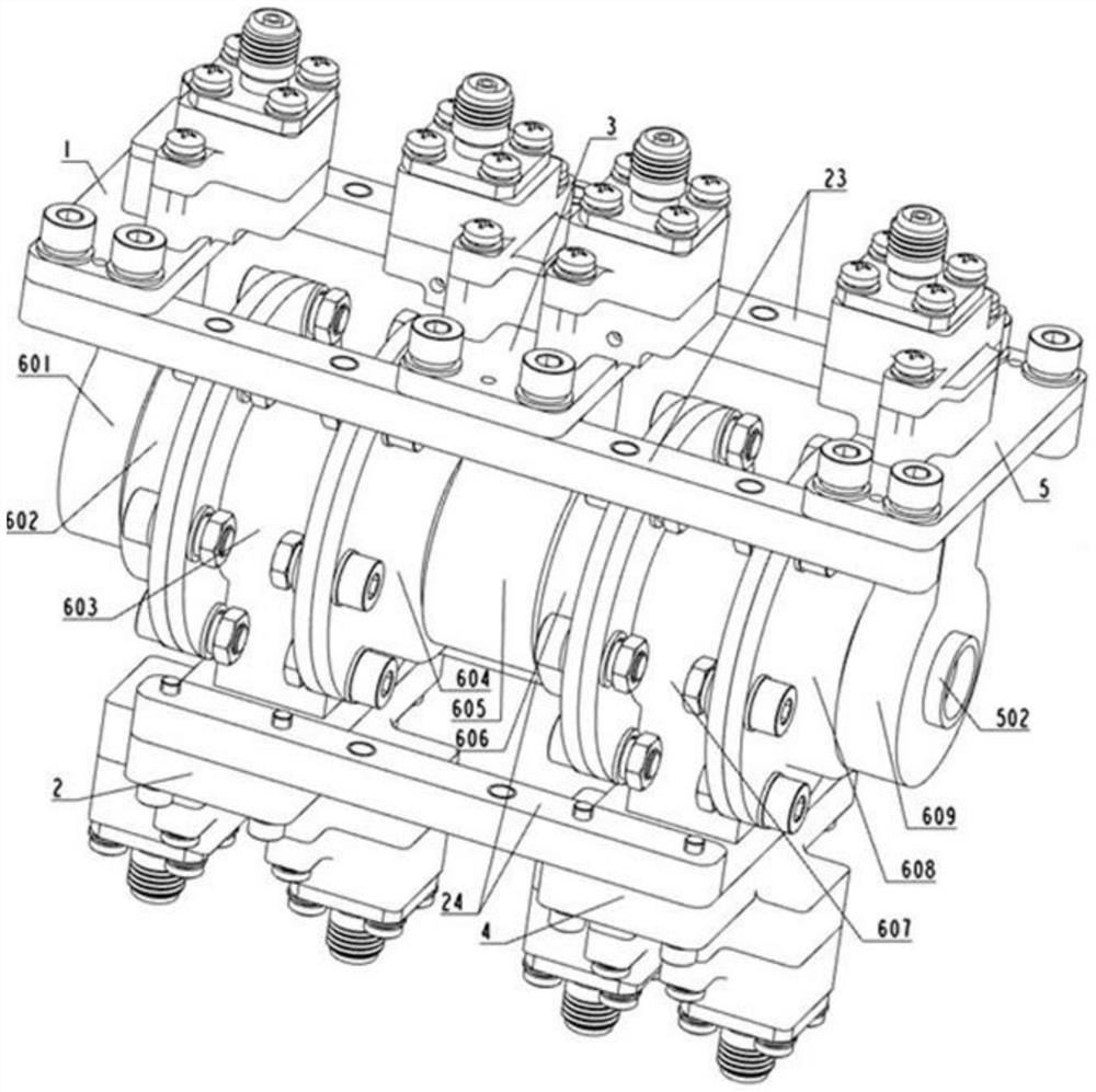
[0075] like image 3 , Figure 4 Distance image 3 Stereoscopic view of the installation structure of the four-channel rotation joint of the star-loaded dual-band; Figure 4 The mounting structure exploding of the four-channel rotation joint of the star-loaded dual-band; preferably, the star-loaded dual-band four-channel rotary joint includes further include a first conformal tool 23 and a second protocol tool 24, The first single waveguide rotor 1, the dual waveguide rotor 3 and the second single waveguide rotor 5 are secured by the first conformal tool 23, the first dual wavefront, and the second The double wave guide 4 is connected to the second conformal tooling plate 24 and the second conformal tooling plate 24 as an assembled tooling, and the star-loaded dual band The four-channel rotary joint is required to remove the first splitting tool 23 and the second protocol tool 24.

[0076]The assembly control method of the first conformal tooling plate 23 and the second conformal tool...

Embodiment 3

[0078] like Figure 5 , Image 6 , Figure 7 Distance Figure 5 Stereoscopic view of the structure of the first single waveguide rotor; Image 6 A cross-sectional view of the structure of the first single waveguide rotor; Figure 7 The structural explosive of the first single waveguide rotor.

[0079] correspond Image 6 The first single waveguide rotor 1 includes a first single waveguide rotor body portion and a first coaxial waveguide conversion unit 14 (double dotted upper side portion), the first single waveguide rotor body portion and the first Coaxial waveguide transform unit 14 integrated processing preparation.

[0080] The first single waveguide rotor body portion (double dotted underside) includes the first rectangular waveguide chamber 101, the first cylindrical waveguide chamber 201 and the first rectangular waveguide chamber 101 and the first rectangular waveguide chamber 101 A transition conversion structure portion formed between the first matching block 401 is formed betw...


PUM


Abstract

The invention discloses a space-borne dual-band four-channel rotary joint, comprising a first single-waveguide rotor, a first double-waveguide stator, a double-waveguide rotor, a second double-waveguide stator, a second single-waveguide rotor; a first single-waveguide rotor, a double-waveguide The waveguide rotor and the second single-waveguide rotor are rotors, the first double-waveguide stator and the second double-waveguide stator are stators; the first double-waveguide stator is arranged between the first single-waveguide rotor and the double-waveguide rotor and connected by bearing support, and the second The two double-waveguide stators are arranged between the second single-waveguide rotor and the double-waveguide rotor and are supported and connected by bearings. The rotor and the stator can rotate relatively; the dual-band four-channel rotary joint of the present invention has two high-frequency four-channels of Ka and K frequency bands The rotary joint has the advantages of high operating frequency and a large number of channels. The concentric stacking structure makes each channel independent of each other, ensuring high isolation requirements between channels.

Description

Technical field [0001] The present invention relates to the field of on-based microwave feeder, and more particularly to a star-loaded dual-band four-channel rotary joint. Background technique [0002] The rotation joint is a radio frequency signal in the continuous rotary antenna system to maintain a continuous device, which is a key component in various microwave systems. When the multiplex signal is transmitted between the antenna and the transmitter and the receiver, in order to achieve multi-function and structural optimization of the microwave system, multiple channel rotation with a larger microwave signal channel, and each channel has different frequency bands. joint. [0003] Multi-channel rotary joint is accumulated by a plurality of rotational joints, i.e., the routing joint is falling on the upper side of the other path; or is nestled by a plurality of rotational joints, that is, rotate all the way The joint sleeve is outside the other side of the rotation joint; it c...

Claims


Application Information

Patent Timeline
Patent Type & Authority Patents(China)
IPC IPC(8): H01P1/06H01P1/30
CPCH01P1/062H01P1/30
Inventor 常健张根烜赵克俊刘文科王群杰刘志高杨双根李祥菊彭伟邓书山康成彬王向伟
Owner CHINA ELECTRONIC TECH GRP CORP NO 38 RES INST
Why Eureka
Try Eureka