Satellite-borne dual-band four-channel rotary joint

A rotary joint, dual-band technology, applied in electrical components, circuits, waveguide devices, etc., to improve stability and reliability, ensure effective clearance, and high precision

Active Publication Date: 2021-06-04
CHINA ELECTRONIC TECH GRP CORP NO 38 RES INST
View PDF10 Cites 3 Cited by
  • Summary
  • Abstract
  • Description
  • Claims
  • Application Information

AI Technical Summary

Problems solved by technology

[0004] Most of the existing microwave rotary joints are ground-based communication products, and their structures mainly include single-channel, dual-channel and multi-channel forms. In the space environment, multi-channel rotary joint products have certain limitations.

Method used


Image

  • Satellite-borne dual-band four-channel rotary joint
  • Satellite-borne dual-band four-channel rotary joint
  • Satellite-borne dual-band four-channel rotary joint

Examples


Embodiment 1

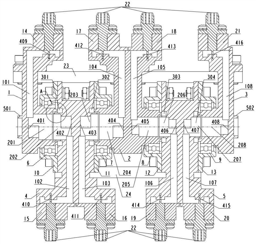
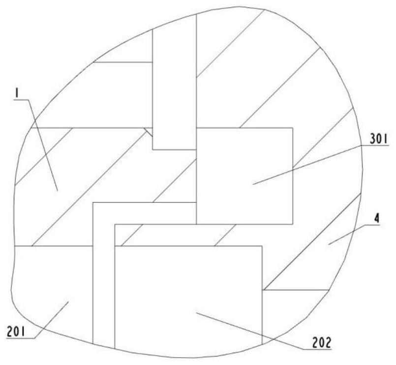
[0042] Such as figure 1 , figure 2 as shown, figure 1 It is a structural sectional view of the spaceborne dual-band four-channel rotary joint; figure 2 for figure 1 Partial structural view of A (choke slot) in middle.

[0043] The space-borne dual-band four-channel rotary joint of the present invention includes a first single-waveguide rotor 1, a first double-waveguide stator 2, a double-waveguide rotor 3, a second double-waveguide stator 4, a second single-waveguide rotor 5, and a first bearing 6. , the second bearing 7, the third bearing 8, the fourth bearing 9, the first bearing cover 10, the second bearing cover 11, the third bearing cover 12, the fourth bearing cover 13.

[0044] The first single-waveguide rotor 1, the double-waveguide rotor 3 and the second single-waveguide rotor 5 are rotors, the first double-waveguide stator 2 and the second double-waveguide stator 4 are stators, and the rotor It is supported and connected with the stator through the first beari...

Embodiment 2

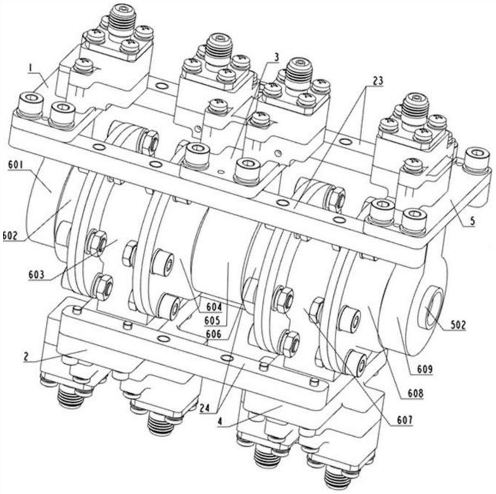
[0075] Such as image 3 , Figure 4 as shown, image 3 It is a three-dimensional view of the installation structure of the spaceborne dual-band four-channel rotary joint; Figure 4 It is an exploded view of the installation structure of the space-borne dual-band four-channel rotary joint; preferably, the space-borne dual-band four-channel rotary joint also includes a first shape-conforming tooling plate 23 and a second shape-keeping tooling plate 24, The first single-waveguide rotor 1, the double-waveguide rotor 3 and the second single-waveguide rotor 5 are connected and fixed through the first conformal tooling plate 23, and the first double-waveguide stator 2 and the second The double-waveguide stator 4 is connected and fixed through the second shape-conserving tooling plate 24, the first shape-keeping tooling plate 23 and the second shape-keeping tooling plate 24 are tooling for assembling and conforming to the shape, and the space-borne dual-band After the four-channel ...

Embodiment 3

[0078] Such as Figure 5 , Figure 6 , Figure 7 as shown, Figure 5 is a structural perspective view of the first single waveguide rotor; Figure 6 is a structural sectional view of the first single waveguide rotor; Figure 7 is an exploded view of the structure of the first single waveguide rotor.

[0079] correspond Figure 6 , the first single-waveguide rotor 1 includes a first single-waveguide rotor body part and a first coaxial waveguide conversion part 14 (upper part on double dot-dash line), the first single-waveguide rotor body part and the first The coaxial waveguide transformation part 14 is obtained through integral processing.

[0080] The main body part of the first single waveguide rotor (the lower part of the dot-dash line) includes the first rectangular waveguide cavity 101, the first cylindrical waveguide cavity 201, and the first rectangular waveguide cavity 101 and the first rectangular waveguide cavity 101. A transitional transformation structure pa...


PUM


Abstract

The invention discloses a satellite-borne dual-band four-channel rotary joint which comprises a first single-waveguide rotor, a first dual-waveguide stator, a dual-waveguide rotor, a second dual-waveguide stator and a second single-waveguide rotor. The first single-waveguide rotor, the double-waveguide rotor and the second single-waveguide rotor are rotors, and the first double-waveguide stator and the second double-waveguide stator are stators; the first double-waveguide stator is arranged between the first single-waveguide rotor and the double-waveguide rotor and is supported and connected through a bearing, the second double-waveguide stator is arranged between the second single-waveguide rotor and the double-waveguide rotor and is supported and connected through a bearing, and the rotors and the stators can rotate relatively. The dual-band four-channel rotary joint is a Ka-high-band four-channel rotary joint and a K-high-band four-channel rotary joint and has the advantages of being high in working frequency and large in number of channels, the channels are independent of one another due to the concentric stacking structure, and the requirement for high isolation between the channels is met.

Description

technical field [0001] The invention relates to the field of satellite-borne microwave feeder technology, in particular to a satellite-borne dual-frequency-band four-channel rotary joint. Background technique [0002] The rotary joint is a device that keeps the radio frequency signal continuous in the continuous rotating antenna system, and is a key component in various microwave systems. When multiple signals are transmitted between the antenna, the transmitter, and the receiver, in order to realize the multi-function and structural optimization of the microwave system, it is often necessary to use a multi-channel rotary with more microwave signal channels and each channel has a different frequency band. joint. [0003] The multi-channel rotary joint is formed by concentric stacking of multiple rotary joints, that is, one rotary joint is placed on top of another rotary joint; or it is formed by concentric nesting of multiple rotary joints, that is, one rotary joint The jo...

Claims


Application Information

Patent Timeline
Patent Type & Authority Applications(China)
IPC IPC(8): H01P1/06H01P1/30
CPCH01P1/062H01P1/30
Inventor 常健张根烜赵克俊刘文科王群杰刘志高杨双根李祥菊彭伟邓书山康成彬王向伟
Owner CHINA ELECTRONIC TECH GRP CORP NO 38 RES INST
Why Eureka
Try Eureka