Yarn conveying and pulling mechanism

A pulling mechanism and yarn technology are applied in the fields of textile processing machinery and equipment, and yarn shaping production and processing. Reasonable structure design, improve efficiency and quality, fully and efficiently pull the effect of shaping processing

Pending Publication Date: 2018-09-28
嘉兴市华益股份有限公司
View PDF9 Cites 15 Cited by
  • Summary
  • Abstract
  • Description
  • Claims
  • Application Information

AI Technical Summary

Problems solved by technology

In the process of yarn production and processing, it is necessary to pull and shape the dyed yarn, especially for the yarn with elastic texture. During the pulling process, the heating cannot be carried out synchronously during the pulling and setting process of the yarn, which affects the quality of the yarn setting, and it is difficult for the existing yarn pulling mechanism to pull the yarn in segments during the pulling process of the yarn. Pulling makes it difficult for the yarn to be fully and efficiently drawn and shaped, which affects the quality of yarn production and processing, and cannot meet the needs of production and use.

Method used


Image

  • Yarn conveying and pulling mechanism
  • Yarn conveying and pulling mechanism
  • Yarn conveying and pulling mechanism

Examples


Embodiment Construction

[0014] In order to further describe the present invention, a specific implementation of a yarn conveying and pulling mechanism will be further described below in conjunction with the accompanying drawings. The following examples are explanations of the present invention and the present invention is not limited to the following examples.

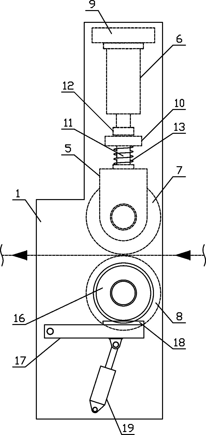
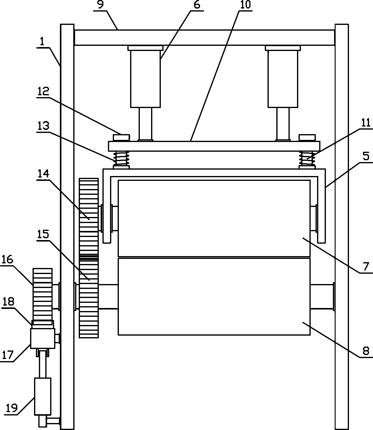
[0015] Such as figure 1 As shown, a yarn conveying and pulling mechanism of the present invention includes a fixed bracket 1, a wire feeding mechanism 2, a pulling mechanism 3 and a wire mechanism 4, and the wire feeding mechanism 2, the pulling mechanism 3 and the wire mechanism 4 are sequentially arranged along the horizontal direction Set on the fixed bracket 1. Such as figure 2 , image 3 As shown, the wire feeding mechanism 2 of the present invention includes a lifting bracket 5, a lifting cylinder 6, an upper yarn pressing guide roller 7 and a lower yarn bearing guide roller 8, and the upper end of one side of the fixed bracket 1 is ...


PUM


Abstract

The invention discloses a yarn conveying and pulling mechanism, and belongs to the field of textile processing mechanical equipment. According to the yarn conveying and pulling mechanism, a yarn feeding mechanism, a pulling mechanism and a yarn guide mechanism are arranged on a fixing support in sequence in the horizontal direction. A lower yarn bearing guide roller is connected with the portion,located on the lower side of an upper yarn press guide roller, of the fixing support in a horizontal rotation mode. A shaping rotating drum is connected to the portion, located between a front yarn guide roller and a rear yarn guide roller, of the fixing support in a horizontal rotation mode, and a heat-conducting oil pipe is arranged at the shaft ends of the two sides of the shaping rotating drumin a communicating mode. Pulling guide plates are arranged in pulling guide grooves in a sliding mode in the circular arc direction, and the pulling guide grooves are formed in the two sides of the shaping rotating drum. One end of one pulling rotating roller and the same end of the other pulling rotating roller are connected to the pulling guide plates on the two sides of the fixing support in arotating mode correspondingly. A yarn discharging guide roller is connected to the portion, located on one side of an adjusting support, of the fixing support in a horizontal rotation mode. The yarnconveying and pulling mechanism is reasonable in structural design, can efficiently and accurately convey yarn, and can conduct stable pulling shaping on the yarn section by section in the conveying process, the degree of automation of yarn processing is improved, and the requirements of production and usage are met.

Description

technical field [0001] The invention belongs to the field of textile processing machinery and equipment, and in particular relates to a yarn transmission and pulling mechanism, which is mainly used in the field of yarn shaping production and processing. Background technique [0002] With the development of the production industry and the improvement of people's living standards, people have higher and higher requirements for textile materials. High-end textiles can be woven from high-quality textile materials to meet people's needs. Textile materials refer to fibers and fiber products, which are specifically manifested as fibers, yarns, fabrics and their composites. In modern textiles, the research and development of new textile materials, especially the development and use of nanofibers, has broken through the traditional textile materials. Conceptually, textile materials have become an important component of soft matter materials. Yarn is an important textile material. Ya...

Claims


Application Information

Patent Timeline
Patent Type & Authority Applications(China)
IPC IPC(8): B65H51/06B65H57/14D02J13/00
CPCD02J13/005B65H51/06B65H57/14B65H2701/31
Inventor 杨利强
Owner 嘉兴市华益股份有限公司
Why Eureka
Try Eureka