Brushless generator

A technology of generators and turntables, applied in the direction of electrical components, electromechanical devices, circuit devices, etc., can solve problems such as replacement and maintenance, poor contact, accidents, etc., and achieve the effect of stable transmission and stable excitation current

Inactive Publication Date: 2016-05-25
朱小菊
View PDF3 Cites 1 Cited by
  • Summary
  • Abstract
  • Description
  • Claims
  • Application Information

AI Technical Summary

Problems solved by technology

[0002] For the current generators, in order to meet the high-power power generation operation, the rotor is usually made into an electromagnet, and the stator winding is used as a generator coil to output current; in order to make the rotor core form a strong magnetic field, the rotor winding needs to be excited ; and because the rotor is in the process of continuous rotation, it is necessary to transmit power to the rotor winding through the brush. Under the action of long-term contact friction and working conditions, the contact between the brush and the rotor winding is more likely to be poor due to wear or pollution. This will seriously affect the efficiency of the motor, and even cause accidents due to electric sparks; for this reason, it is necessary to replace and maintain the brush structure regularly, which will increase the maintenance cost of the motor

Method used


Image

  • Brushless generator
  • Brushless generator
  • Brushless generator

Examples


Embodiment 1

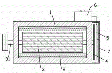
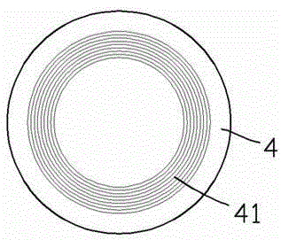
[0016] exist figure 1 , figure 2 In the first embodiment shown, the brushless generator includes a casing 1, a stator 2, and a rotor 3; the stator 2 includes a stator core and a stator winding; the rotor 3 includes a rotating shaft 31, a rotor core, and a rotor winding; The rotating shaft 31 protrudes from the rear end of the casing 1, and is fixedly connected to a non-conductive turntable 4 outside the casing; the turntable 4 is provided with a turntable coil 41 concentric with the turntable 4, and two of the turntable coils 41 The output end is electrically coupled to the rotor winding; the rear end of the housing is also fixed with a non-conductor fixed disk 5 that is close to the turntable 4 and facing each other. 41 fixed disk coils facing each other, the fixed disk coils are connected in series with a fixed capacitor and then connected to a secondary coil of a transformer power supply, the fixed disk coils, fixed capacitors, and secondary coils form an input-side LC os...

Embodiment 2

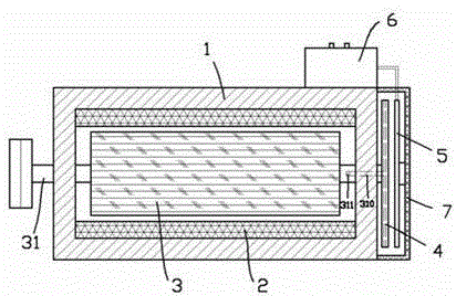
[0020] for image 3 , Figure 4 The second embodiment shown differs from the first embodiment in that: the inside of the turntable 4 is formed with a radial through hole 40, the outer end of the radial through hole 40 runs through the peripheral surface of the turntable 4, and the inner end It communicates with the shaft hole 310 inside the rotor shaft 31 , one end of the shaft hole 310 is blocked, and the other end communicates with the inside of the casing 1 through the wall hole 311 on the shaft 31 . According to the second embodiment, during the rotation of the turntable 4 with the rotor 3, the radial through holes 40 in the turntable 4 are exhausted by the centrifugal force of the air, and the hot air in the inner space of the casing 1 is sucked away to clean the inside of the casing 1. Good cooling.


PUM


Abstract

The invention provides a brushless generator. The brushless generator comprises a shell, a stator and a rotor, wherein the stator comprises a stator iron core and a stator winding; the rotor comprises a rotating shaft, a rotor iron core and a rotor winding; the rotating shaft extends out of the back end of the shell and is connected with a rotary plate; the rotary plate is provided with a rotary plate coil, and the output end of the rotary plate coil is electrically coupled with the rotor winding; a fixed disk that is close to the rotary plate and directly faces to the rotary plate is further fixed at the back end of the shell; a fixed disk coil, directly facing to the rotary plate coil, is arranged on the fixed disk; the fixed disk coil is serially connected with a fixed capacitor, and then is connected to a secondary coil of a transformer power supply; the fixed disk coil, the fixed capacitor and the secondary coil form an input side LC oscillating circuit; the rotary disk coil is connected with a rotating capacitor, and then is connected to the rotor winding; the rotary plate coil, the rotating capacitor and the rotor winding form an output side LC oscillating circuit; and the input side LC oscillating circuit and the output side LC oscillating circuit have the equivalent inherent frequency. The generator can provide excitation current to the rotor winding on the basis of the brushless structure so as to lower the motor fault rate and maintenance cost.

Description

technical field [0001] The invention relates to the field of electromechanical equipment, in particular, a generator. Background technique [0002] For the current generators, in order to meet the high-power power generation operation, the rotor is usually made into an electromagnet, and the stator winding is used as a generator coil to output current; in order to make the rotor core form a strong magnetic field, the rotor winding needs to be excited ; and because the rotor is in the process of continuous rotation, it is necessary to transmit power to the rotor winding through the brush. Under the action of long-term contact friction and working conditions, the contact between the brush and the rotor winding is more likely to be poor due to wear or pollution. This will seriously affect the efficiency of the motor, and even cause accidents due to electric sparks; for this reason, the brush structure needs to be replaced and maintained regularly, which will increase the main...

Claims


Application Information

Patent Timeline
IPC IPC(8): H02K29/00H02K7/20H02K11/20H02J50/12
CPCH02K29/00H02K7/20H02K11/00
Inventor 朱小菊
Owner 朱小菊
Why Eureka
Try Eureka