
3D shooting method and device, storage medium and mobile terminal

A technology of a mobile terminal and a shooting method, applied in the fields of devices, mobile terminals, and 3D shooting methods, can solve problems such as difficult 3D shooting, different parameters of a first camera and a second camera, and achieve simplified calibration procedures, low 3D shooting costs, Simple to use effects

Active Publication Date: 2021-06-04
GUANGDONG FUTURE TECH CO LTD
View PDF7 Cites 0 Cited by
  • Summary
  • Abstract
  • Description
  • Claims
  • Application Information

AI Technical Summary

Problems solved by technology

[0005] In order to solve the technical problem that it is difficult to take 3D shots when the parameters of the first camera and the second camera of the above-mentioned mobile terminal are different, the present invention provides a 3D shooting method for a mobile terminal

Method used


Image

  • 3D shooting method and device, storage medium and mobile terminal
  • 3D shooting method and device, storage medium and mobile terminal
  • 3D shooting method and device, storage medium and mobile terminal

Examples


no. 1 example

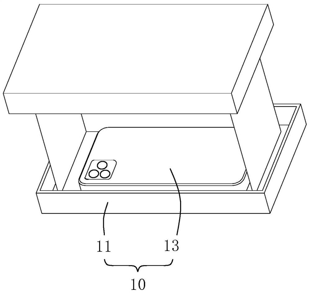
[0057] see figure 1 , figure 1 It is a three-dimensional assembly diagram of a 3D shooting device disclosed in the present invention. The 3D shooting device 10 includes a 3D shooting calibration device 11 and a mobile terminal 13 . Wherein, the mobile terminal 13 may be a mobile terminal such as a smart phone, a tablet computer, a palmtop computer, a notebook computer or a desktop computer, and the present embodiment takes a smart phone as an example.

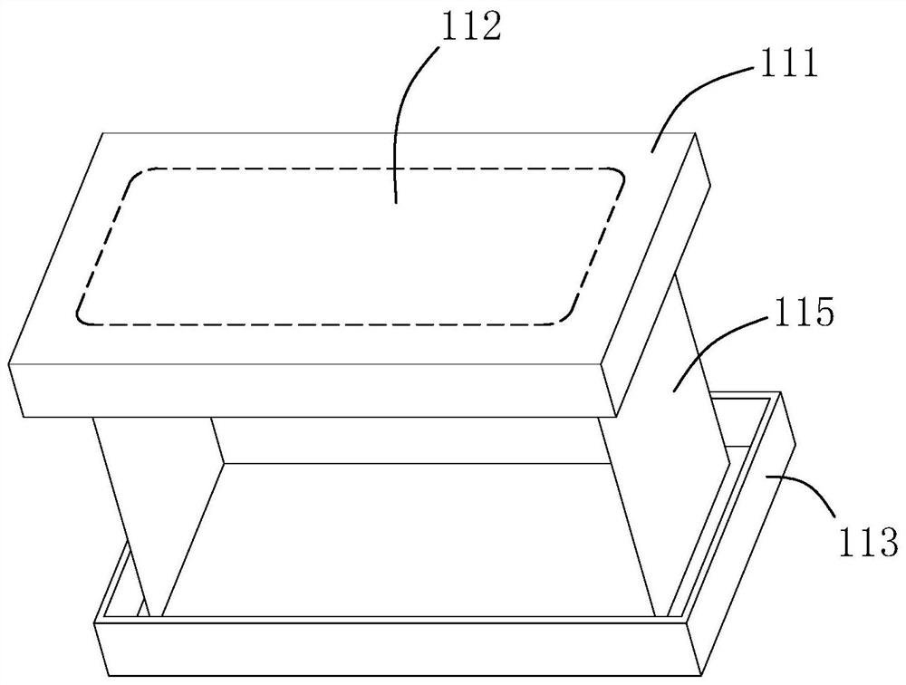
[0058] The 3D shooting calibration device 11 includes an upper cover 111, a 3D shooting calibration pattern 112, a lower cover 113 and a support body 115, such as figure 2 shown.

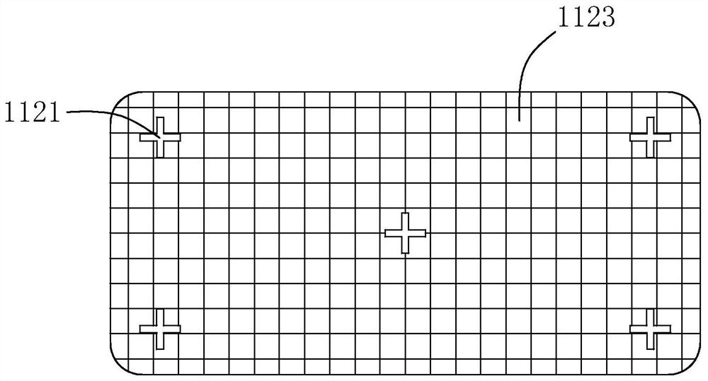
[0059] The 3D shooting calibration pattern 112 is disposed on the inner surface of the upper cover 111 . The 3D shooting calibration pattern 112 includes calibration base points 1121 and color blocks 1123, such as image 3 shown. The number of the calibration base points 1121 is 5, which are respectively located at the four corners and the cen...

no. 2 example

[0104] The mobile terminal 13 is a Huawei P40 Pr+, and the main difference from the first embodiment is that the back of the mobile terminal 13 includes five cameras, specifically a first camera 131, a second camera 133, a third camera 132, a Four cameras 134 and the fifth camera 136, such as Figure 9 shown. Wherein, the first camera 131 is a camera with the largest viewing angle, and the second camera 133 is a camera with the second largest viewing angle.

[0105] The 3D shooting method, principle and advantages of the mobile terminal 13 are the same as those in the first embodiment, and will not be repeated one by one.

[0106] The present invention also provides a readable storage medium, wherein a calibration program and a 3D shooting program are stored in the storage medium, and when the calibration program and the 3D shooting program are run on a computer, the computer executes the above-mentioned 3D video shooting method.

[0107] The present invention also provides...


PUM


Abstract

The invention provides a 3D shooting method for a mobile terminal, and the method comprises the steps: selecting a camera with the largest field angle as a first camera, selecting a camera with the second largest field angle as a second camera, marking the position relation of the first camera and the second camera as LR or RL and TB or BT, recording the distance between the first camera and the second camera, and recording the distance between the first camera and the second camera, and the included angle, when the mobile terminal carries out the transverse shooting, between a connecting line of the first camera and the second camera and a horizontal line, wherein the included angle is between 0 degree and 90 degrees; executing a calibration program; and executing a 3D shooting program. The invention further provides a 3D shooting device, a storage medium and a mobile terminal. The 3D shooting method provided by the invention has the following advantages: 3D shooting can be realized through calibration; the second camera is used as a calibration reference, so that a calibration program can be simplified; adjustment is performed according to the position relation mark, the distance and the included angle, and the method can adapt to random arrangement of the first camera and the second camera on the back of the existing mobile terminal.

Description

technical field [0001] The invention relates to the field of stereoscopic display, in particular to a 3D shooting method, device, storage medium and mobile terminal. Background technique [0002] 3D refers to three-dimensional space. The reason why human vision can distinguish between distance and near depends on the gap between the two eyes. A person's two eyes are about 5 cm apart, and the angles of the two eyes will not be the same when looking at anything except the front. Although the gap is very small, it is transmitted to the brain through the retina, and the brain uses this tiny gap to generate the depth of distance and thus create a three-dimensional effect. Although one eye can see objects, it is not easy to distinguish the distance of objects. According to this principle, if the same image is used to create two images using the difference in the angle of view of the two eyes, and then let each eye see the image on its own side, the brain can produce a three-dim...

Claims


Application Information

Patent Timeline
Patent Type & Authority Applications(China)
IPC IPC(8): H04N13/239H04N13/243H04N13/246H04N13/257H04N13/271
CPCH04N13/246H04N13/257H04N13/239H04N13/243H04N13/271
Inventor 贺曙
Owner GUANGDONG FUTURE TECH CO LTD
Learn More