
Terminal equipment

A technology of terminal equipment and casing, which is applied in the electronic field, can solve problems such as large redundancy, decreased adhesion force, and affecting normal use of mobile phones, and achieve the effect of solving casing slippage

Inactive Publication Date: 2021-06-04
WINGTECH COMM
View PDF0 Cites 0 Cited by
  • Summary
  • Abstract
  • Description
  • Claims
  • Application Information

AI Technical Summary

Problems solved by technology

[0002] With the continuous development of flexible screen technology, terminal devices using folding screens have begun to appear. For example, in the existing folding screen mobile phones, the two shells are connected by a hinge assembly, and then the flexible screen is placed on the two shells. , the two shells can be freely switched between the folded state and the unfolded state; since the mobile phone must be switched between the folded state and the unfolded state at will, the length of the shell assembly composed of the two shells is different in the two states , while the length of the flexible screen is fixed, in order to overcome this difference, the shaft assembly needs to be set as a retractable structure, specifically, a spring structure is provided inside the shaft assembly to compensate for the above-mentioned length in the folded state and the unfolded state The difference is that the spring inside the hinge assembly always generates a tensile stress on the flexible screen to ensure that the flexible screen remains flat in any state. At the same time, the flexible screen is attached to the middle frame through the back glue. In the state, due to the continuous tension of the spring, the adhesive force of the back glue will decrease, causing the flexible screen to slide relative to the middle frame towards the direction of the shaft assembly. In this way, when the mobile phone is in the unfolded state, the flexible screen will slide In the end, the redundant amount is too large, which leads to an arching at the position corresponding to the rotating shaft on the flexible screen, which affects the normal use of the mobile phone

Method used


Image

  • Terminal equipment
  • Terminal equipment
  • Terminal equipment

Examples


Embodiment Construction

[0026] The following will clearly and completely describe the technical solutions in the embodiments of the present invention with reference to the accompanying drawings in the embodiments of the present invention. Obviously, the described embodiments are only part of the embodiments of the present invention, not all of them. Based on the embodiments of the present invention, all other embodiments obtained by persons of ordinary skill in the art without creative efforts fall within the protection scope of the present invention.

[0027] It should be noted that all directional indications (such as up, down, left, right, front, back...) in the embodiments of the present invention are only used to explain the relationship between the components in a certain posture (as shown in the accompanying drawings). Relative positional relationship, movement conditions, etc., if the specific posture changes, the directional indication will also change accordingly.

[0028] In addition, the ...


PUM


Abstract

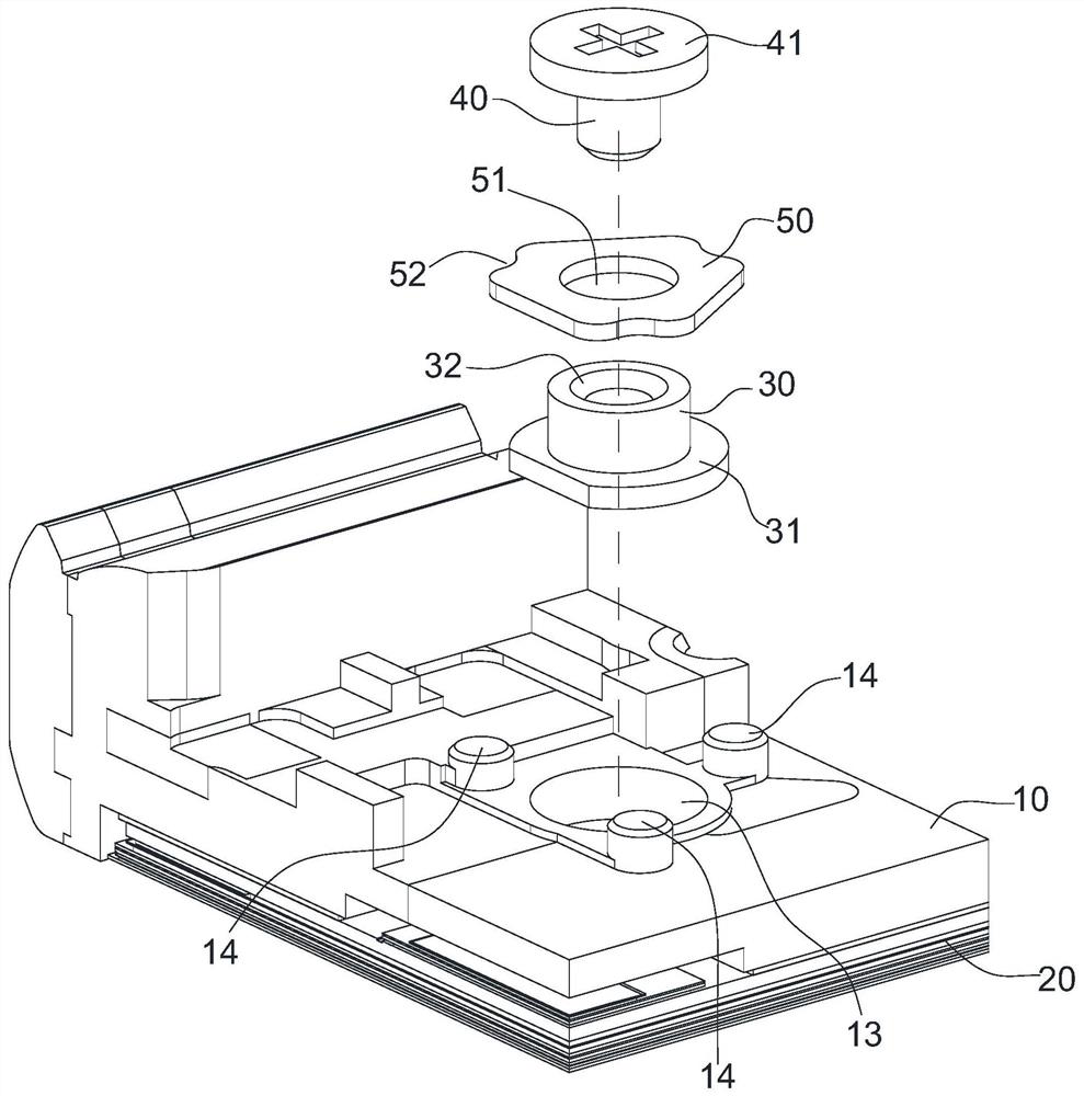
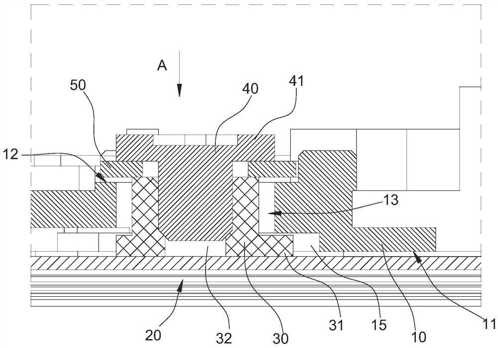
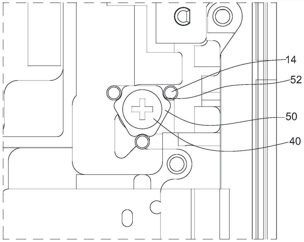
The invention discloses terminal equipment. The terminal equipment comprises a shell, a flexible screen and a fixing part; the shell comprises a lower surface and an upper surface opposite to the lower surface, and the flexible screen is arranged on the lower surface of the shell; a through hole extending from the lower surface to the upper surface is formed in the shell, a fixing column is embedded in the through hole, and the lower end of the fixing column fixedly matches the flexible screen; the fixing part is fixedly connected with the upper end of the fixing column, and a limiting flange located above the upper surface is arranged at the top of the fixing part. A limiting part is arranged on the shell, and the limiting part matches the fixing part to form a limiting assembly used for limiting the fixing part to horizontally move relative to the shell. According to the technical scheme, the flexible screen is tensioned through the fixing column, and the problem that the flexible screen slides relative to the shell is effectively solved.

Description

technical field [0001] The present invention relates to the field of electronic technology, in particular to a terminal device. Background technique [0002] With the continuous development of flexible screen technology, terminal devices using folding screens have begun to appear. For example, in the existing folding screen mobile phones, the two shells are connected by a hinge assembly, and then the flexible screen is placed on the two shells. , the two shells can be freely switched between the folded state and the unfolded state; since the mobile phone must be switched between the folded state and the unfolded state at will, the length of the shell assembly composed of the two shells is different in the two states , while the length of the flexible screen is fixed, in order to overcome this difference, the shaft assembly needs to be set as a retractable structure, specifically, a spring structure is provided inside the shaft assembly to compensate for the above-mentioned l...

Claims


Application Information

Patent Timeline
Patent Type & Authority Applications(China)
IPC IPC(8): H05K5/02
CPCH05K5/0217
Inventor 叶宇峰
Owner WINGTECH COMM
Learn More