Forming mould positioning device for aerospace composite material

A technology of composite materials and forming molds, which is applied in the field of aerospace equipment, can solve the problems of inconvenient operation and large consumption, and achieve the effect of ensuring stability

Inactive Publication Date: 2018-06-12
ZHONGSHAN DEGAOXING INTPROP CENT LLP
View PDF1 Cites 0 Cited by
  • Summary
  • Abstract
  • Description
  • Claims
  • Application Information

AI Technical Summary

Problems solved by technology

So far, although aerospace activities are only the first few steps of human beings leaving the cradle of the earth, their effects have gone far beyond the field of science and technology, and have had extensive and far-reaching impacts on politics, economy, military affairs and even human social life. , where the amount of composite materials used in aerospace is very large, and the forming molds for making these composite materials are generally positioned manually, so skilled workers need a lot of experience, which makes it very inconvenient to operate, and the production The efficiency is very low, so we propose a molding die positioning device for aerospace composite materials to solve the above problems

Method used


Image

  • Forming mould positioning device for aerospace composite material
  • Forming mould positioning device for aerospace composite material
  • Forming mould positioning device for aerospace composite material

Examples


Embodiment Construction

[0018] The following will clearly and completely describe the technical solutions in the embodiments of the present invention with reference to the accompanying drawings in the embodiments of the present invention. Obviously, the described embodiments are only some, not all, embodiments of the present invention. Based on the embodiments of the present invention, all other embodiments obtained by persons of ordinary skill in the art without making creative efforts belong to the protection scope of the present invention.

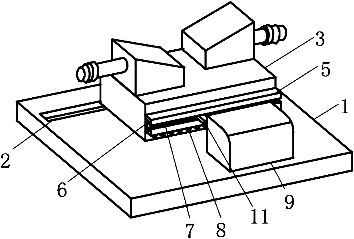
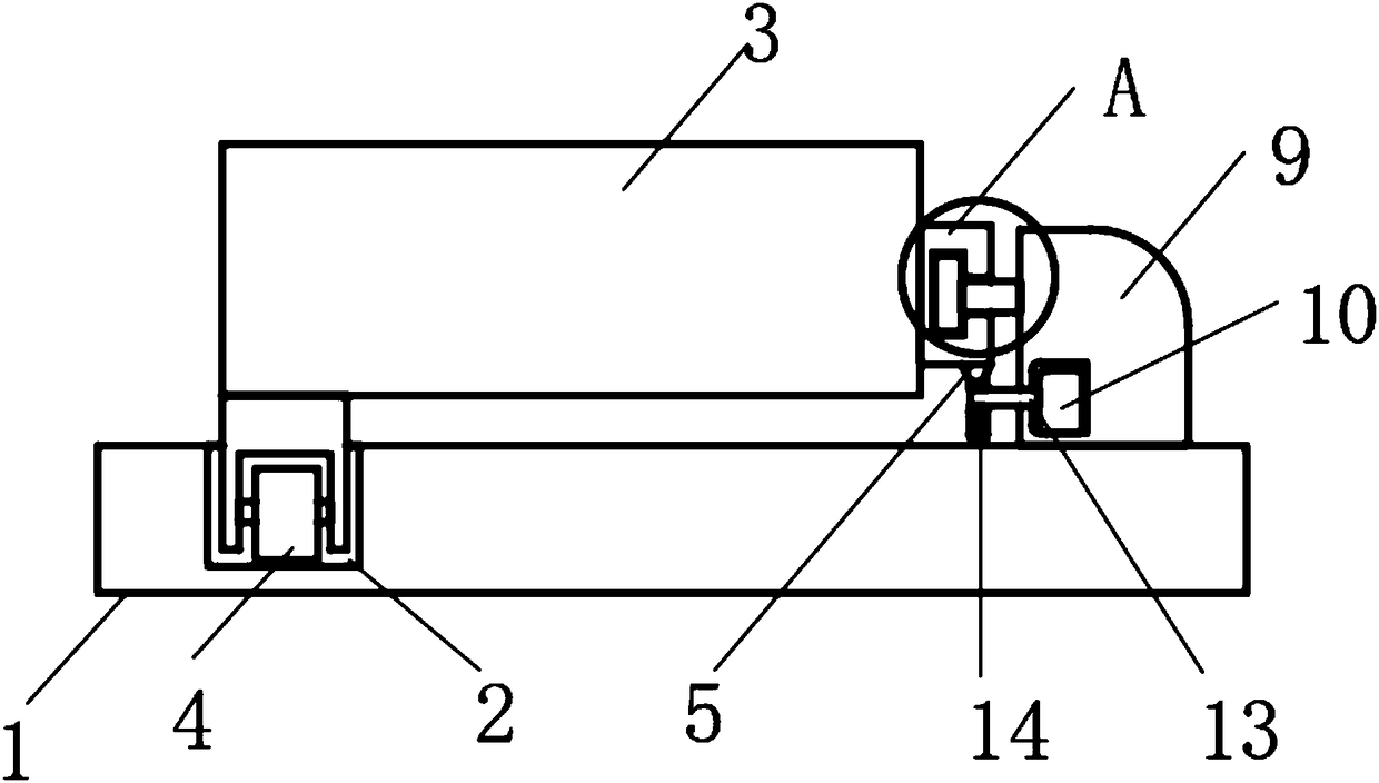
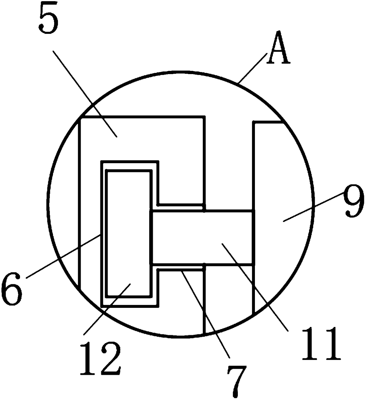
[0019] see Figure 1-3 , the present invention provides a technical solution: a molding die positioning device for aerospace composite materials, including a base 1 and a molding machine 3, a roller groove 2 is opened on one side of the upper surface of the base 1, and a roller groove 2 is provided on the top of the base 1 There is a molding machine 3, the lower surface side of the molding machine 3 is rotatably connected with a roller 4, and the roller 4 is m...


PUM


Abstract

The invention discloses a forming mould positioning device for an aerospace composite material. The forming mould positioning device comprises a base and a forming machine; a roller groove is formed in one side of the upper surface of the base; the forming machine is arranged above the base; and rollers are rotatably connected to one side of the lower surface of the forming machine and rotatably arranged in the roller groove. The roller groove is formed in the upper surface of the base, the forming machine is arranged above the base, the rollers are rotatably arranged on one side of the lowersurface of the forming machine in a front-rear symmetrical mode and rotatably arranged in the roller groove, and thus the purpose of driven moving of the forming machine is achieved. A positioning seat is fixedly mounted on the upper surface of the base, a movable seat is arranged on one side of the forming machine, movable rods are symmetrically arranged on one side of the positioning seat and inserted in movable grooves, meanwhile, positioning blocks are arranged at the ends of the movable rods and slidably arranged in positioning grooves, a motor is arranged on the lower surface of one sideof the positioning seat and drives a gear to rotate, and the gear is engaged with racks, so that the forming machine moves.

Description

technical field [0001] The invention relates to the technical field of aerospace equipment, in particular to a molding die positioning device for aerospace composite materials. Background technique [0002] The development of the aerospace industry is the result of the rapid progress of science and technology and the rapid development of social production in the 20th century. The achievements of aerospace have concentrated many new achievements in science and technology. So far, although aerospace activities are only the first few steps of human beings leaving the cradle of the earth, their functions have gone far beyond the field of science and technology, and have had extensive and far-reaching impacts on politics, economy, military affairs and even human social life. , where the amount of composite materials used in aerospace is very large, and the forming molds for making these composite materials are generally positioned manually, so skilled workers need a lot of exper...

Claims


Application Information

Patent Timeline
Patent Type & Authority Applications(China)
IPC IPC(8): B29C33/30
CPCB29C33/303
Inventor 谢小坚梁荣强
Owner ZHONGSHAN DEGAOXING INTPROP CENT LLP
Why Eureka
Try Eureka