
Part fixture used in drill press

A technology for fixing fixtures and parts, applied in metal processing machinery parts, clamping, positioning devices, etc., can solve the problems of deviation in processing, affecting dimensional accuracy, and unrestricted degrees of freedom, and achieve the effect of preventing deviation.

Inactive Publication Date: 2013-04-10
WUJIANG HEXI MACHINERY
View PDF4 Cites 0 Cited by
  • Summary
  • Abstract
  • Description
  • Claims
  • Application Information

AI Technical Summary

Problems solved by technology

In order to drill holes on the bottom plate of the part, at present, the part is fixed by a spacer fixed on the base and a positioning pin pierced in the spacer and the buckle, because the degree of freedom of the part in the direction of rotation around the axis of the positioning pin is limited. Limited, so there may be deviations during processing, affecting dimensional accuracy

Method used


Image

  • Part fixture used in drill press
  • Part fixture used in drill press
  • Part fixture used in drill press

Examples


Embodiment Construction

[0013] The preferred specific embodiments of the present invention will be described below in conjunction with the accompanying drawings.

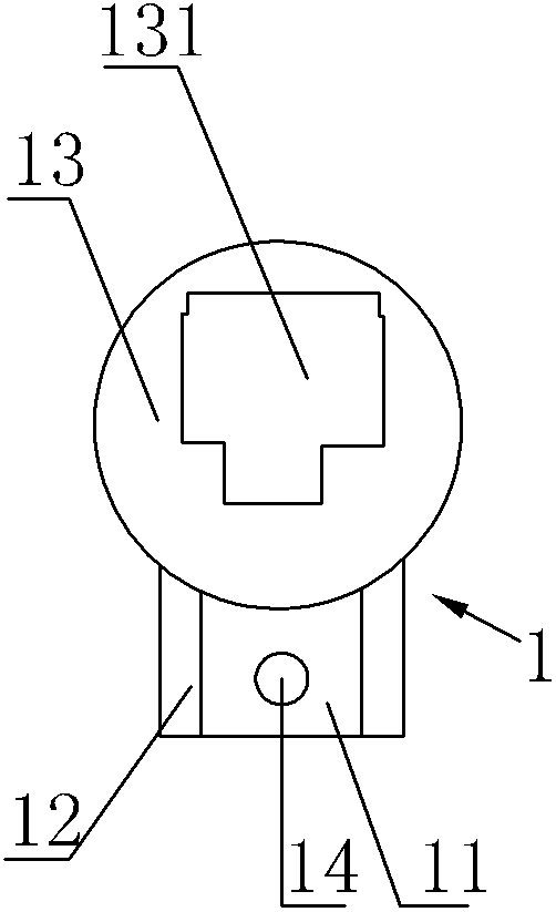
[0014] Such as image 3 , 4 As shown, a part 1 used on a sewing machine has a strip-shaped bottom plate 11, a wing plate 12 symmetrically arranged on both sides of the bottom plate 11, and a buckle 13 fixedly connected to the upper end surface of the bottom plate 11. The wing plate The upper surface of 12 is lower than the upper surface of bottom plate 11.

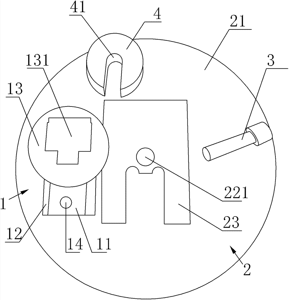
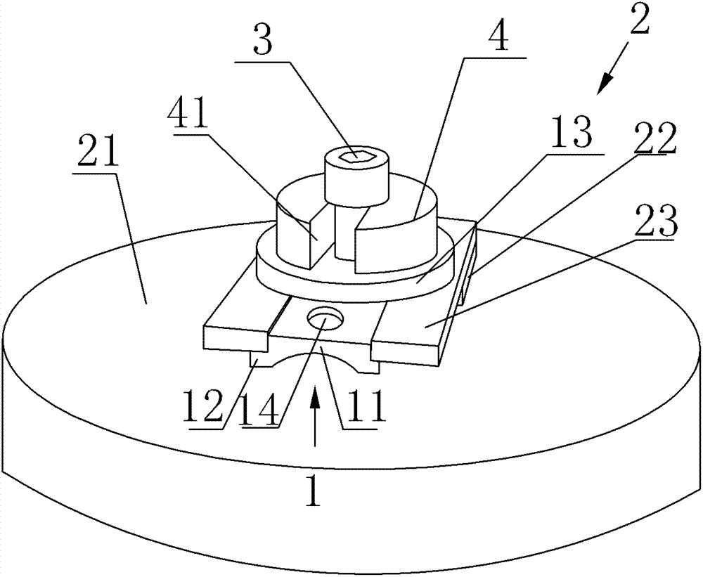
[0015] In order to fix the above parts 1, and drill a round hole 14 on the base plate 11, the present embodiment provides a clamp 2, such as figure 1 , 2 As shown, the clamp 2 includes a base 21, a pad 22 fixed on the base 21, a pressing block 23 fixed on the upper surface of the pad 22, one end of the pressing block 23 is fixed on the pad 22, and the other end is Out of the pad 22 and suspended on the base 21, the part of the pressure block 23 protruding from the pad 22 i...


PUM


Abstract

The invention provides a part fixture used in a drill press. In the invention, the part is provided with a strip bottom plate, wing plates symmetrically arranged at two sides of the bottom plate as well as a buckle fixedly connected with the upper end surface of the bottom plate, wherein, the upper surface of each wing plate is lower than that of the bottom plate; the fixture comprises a base, a cushion block fixed on the base as well as a pressing block fixed on the upper surface of the cushion block, wherein, one end of the pressing block is fixed on the cushion block, the other end of the pressing block extends out of the cushion block and is hung on the base, and a clamping groove is arranged at the part of the cushion block extending out of the pressing block; the bottom plate is clamped in the clamping groove, and the wing plates are clamped between the pressing block and the base; and the lower surface of the buckle is closely clung to the upper surface of the pressing block. The part fixture has the beneficial effects that the part is arranged into the space formed by the pressing block and the base so as to restrict the freedom degree of the part in rotation around the axis of a locating pin, thus effectively preventing deviation generated during the part machining process.

Description

technical field [0001] The invention relates to a component fixing fixture used on a drilling machine. Background technique [0002] A part used on a sewing machine, the part has a strip-shaped bottom plate, wing plates symmetrically arranged on both sides of the bottom plate, and a buckle fixedly connected with the upper surface of the bottom plate, and the upper surface of the wing plate is lower than the upper surface of the bottom plate. In order to drill holes on the bottom plate of the part, at present, the part is fixed by a spacer fixed on the base and a positioning pin pierced in the spacer and the buckle, because the degree of freedom of the part in the direction of rotation around the axis of the positioning pin is limited. Limits, so there may be deviations during processing, affecting dimensional accuracy. Contents of the invention [0003] The object of the present invention is to provide a fixture for fixing parts on a drilling machine. [0004] In order t...

Claims


Application Information

Patent Timeline
Patent Type & Authority Patents(China)
IPC IPC(8): B23Q3/06
Inventor 孙和喜
Owner WUJIANG HEXI MACHINERY
Learn More