Clamping device and clamping method for processing photoelectric components

A technology for optoelectronic components and clamping devices, applied in workpiece clamping devices, auxiliary devices, metal processing equipment, etc., can solve the problems of cost loss, loss of human and material resources, etc. Effect

Active Publication Date: 2021-06-08
ZHANGPU BISU LIGHTING TECH
View PDF8 Cites 0 Cited by
  • Summary
  • Abstract
  • Description
  • Claims
  • Application Information

AI Technical Summary

Problems solved by technology

[0002] Photoelectric devices refer to devices made according to the photoelectric effect, called photoelectric devices, also known as photosensitive devices. When processing photoelectric components, welding and installation are generally required. Different processing methods require different fixing methods, and different fixing methods require Different degrees of freedom are limited, and because many optoelectronic components are to be installed and welded, the fixing and installation methods of each optoelectronic component are different. When using ordinary fixtures for installation and welding, or offset, excessive Different situations such as loose movement, over-tight damage, etc. will cause loss in cost. If the problem has not been solved, the working hours will cause a lot of manpower and material loss.

Method used


Image

  • Clamping device and clamping method for processing photoelectric components
  • Clamping device and clamping method for processing photoelectric components
  • Clamping device and clamping method for processing photoelectric components

Examples


Embodiment 1

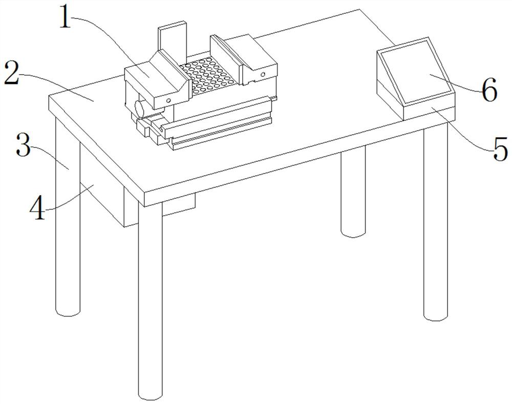
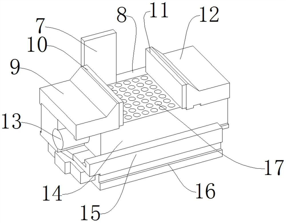
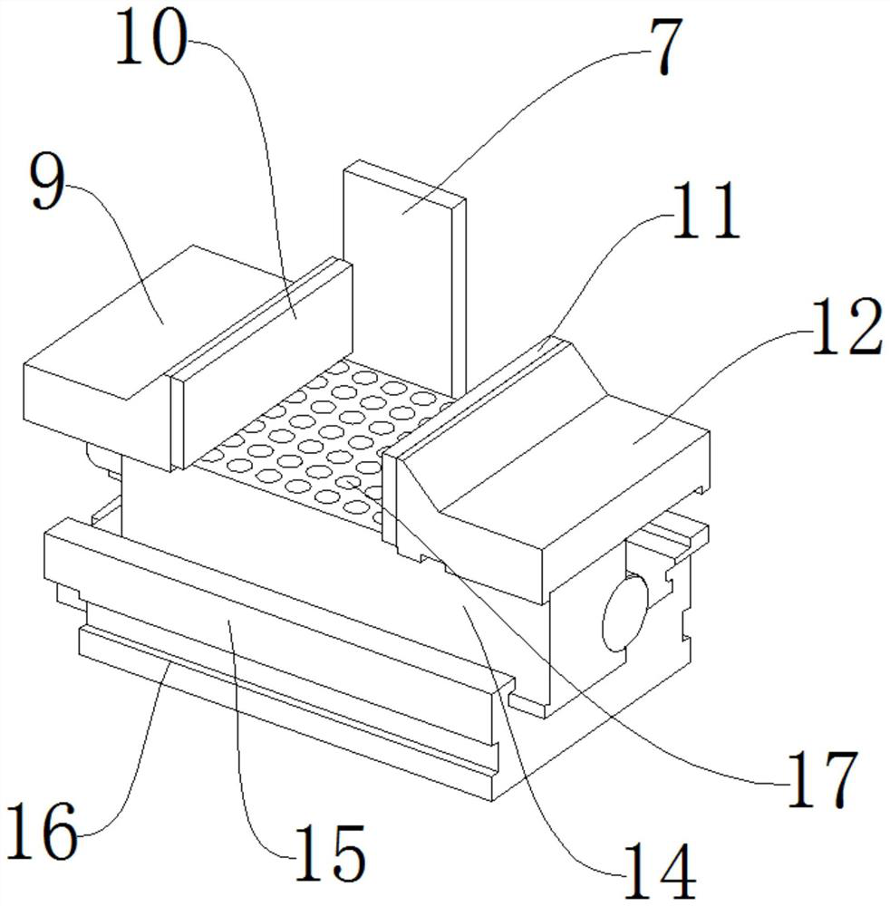
[0051] like Figure 1-Figure 12 As shown, a clamping device for processing photoelectric components includes a clamping mechanism 1, a workbench 2, a suction mechanism 22, and a center platform 14. The upper end of the workbench 2 is provided with a clamping mechanism 1, and the workbench 2 starts from Bearing function, the clamping mechanism 1 plays a clamping role. The clamping mechanism 1 is connected to the workbench 2 by bolts. The clamping mechanism 1 includes a first clamp 9, a first clamp 10, a second clamp 11, and a second clamp 12 , one side of the first clamp 9 is provided with a first clamping plate 10, the first clamping clamp 9 plays a clamping role, the first clamping plate 10 plays a protective role, the first clamping plate 10 is connected to the first clamping clamp 9 by bolts, and the first clamping plate 10 One side is provided with a second splint 11, the second splint 11 plays a protective role, and one side of the second splint 11 is provided with a seco...

Embodiment 2

[0053] The difference between this embodiment and embodiment 1 is:

[0054] The electrical box 4 outside is provided with support leg 3, and support leg 3 is connected to workbench 2 by bolt, and support leg 3 plays a supporting role, and support leg 3 is connected with workbench 2 by bolt, has guaranteed the stability of equipment.

[0055] The present invention also provides a method for using a clamping device for processing photoelectric components, which is applied to the above-mentioned clamping device for processing photoelectric components. The specific waste recovery method is as follows:

[0056] a. First adjust the position of the baffle 7 on the baffle slide rail 8, then use the control panel 6 to control the controller 36 to turn on the equipment, and place the photoelectric components to be clamped on the center table 14.

[0057] b, the photoelectric component presses the sucker 23, the first pressure sensor 25 at the lower end of the sucker 23 feels the pressur...


PUM


Abstract

The invention discloses a clamping device and a clamping method for processing photoelectric components, including a clamping mechanism, a workbench, a suction mechanism, and a center platform. The upper end of the workbench is provided with the clamping mechanism. The clamping mechanism is connected to the workbench by bolts, and the clamping mechanism includes a first clamp, a first clamping plate, a second clamping plate, and a second clamping clamp. One side of the first clamping clamp is provided with the A first splint, the first splint is connected to the first clamp by bolts, and the second splint is arranged on one side of the first splint. The beneficial effect is that the structure is reasonable, the device adopts bilateral clamping, and the fixation method of the lower end is sucked tightly, which limits the degree of freedom and does not affect subsequent processing, and is easy to operate. , High safety, the equipment adopts automatic induction method to select the clamping force, which ensures the safety of photoelectric components.

Description

technical field [0001] The invention relates to the field of processing photoelectric components, in particular to a clamping device and a clamping method for processing photoelectric components. Background technique [0002] Photoelectric devices refer to devices made according to the photoelectric effect, called photoelectric devices, also known as photosensitive devices. When processing photoelectric components, welding and installation are generally required. Different processing methods require different fixing methods, and different fixing methods require Different degrees of freedom are limited, and because many optoelectronic components are to be installed and welded, the fixing and installation methods of each optoelectronic component are different. When using ordinary fixtures for installation and welding, or offset, excessive Different situations such as loose movement, over-tight damage, etc. will cause loss in cost. If the problem is not resolved, the working ho...

Claims


Application Information

Patent Timeline
Patent Type & Authority Patents(China)
IPC IPC(8): B25B11/00B23K37/04
CPCB23K37/0443B25B11/00B25B11/005
Inventor 蔡天平
Owner ZHANGPU BISU LIGHTING TECH
Why Eureka
Try Eureka